
1. Overview of FMR20 RS485 Reading
FMR20 is a compact radar level transmitter launched by Endress+Hauser, supporting RS485 Modbus RTU digital communication. Through the RS485 interface, users can upload measured values such as level and distance directly to PLC, DCS, or host computer systems.
This article introduces the complete operation process from wiring and Bluetooth configuration to Modbus reading step by step, suitable for engineering technicians and procurement personnel for reference.
2. Wiring and Power-On
2.1 Wiring Diagram
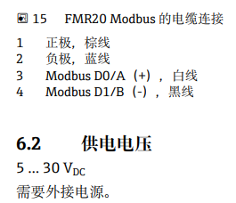
Please refer to the figure below for the RS485 terminal definitions of FMR20. Ensure that the power supply and communication cables are correctly connected to avoid equipment damage caused by reverse connection.
3. Smartblue Bluetooth Configuration
3.1 Connecting the Device
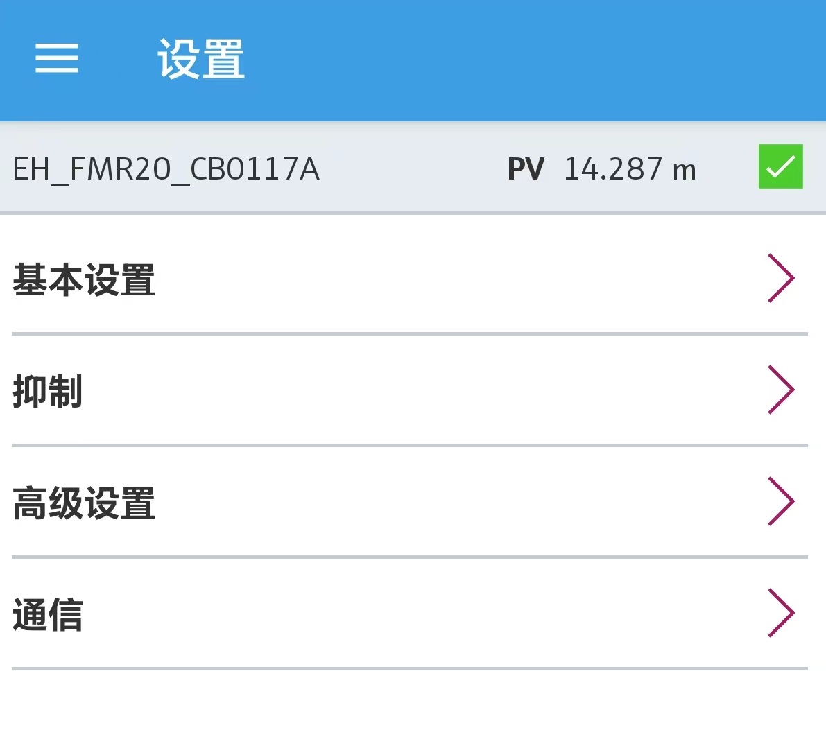
After power-on, open the Smartblue app on your phone, search for and connect to FMR20. The default username is admin, and the password is the device serial number.
3.2 Basic Settings
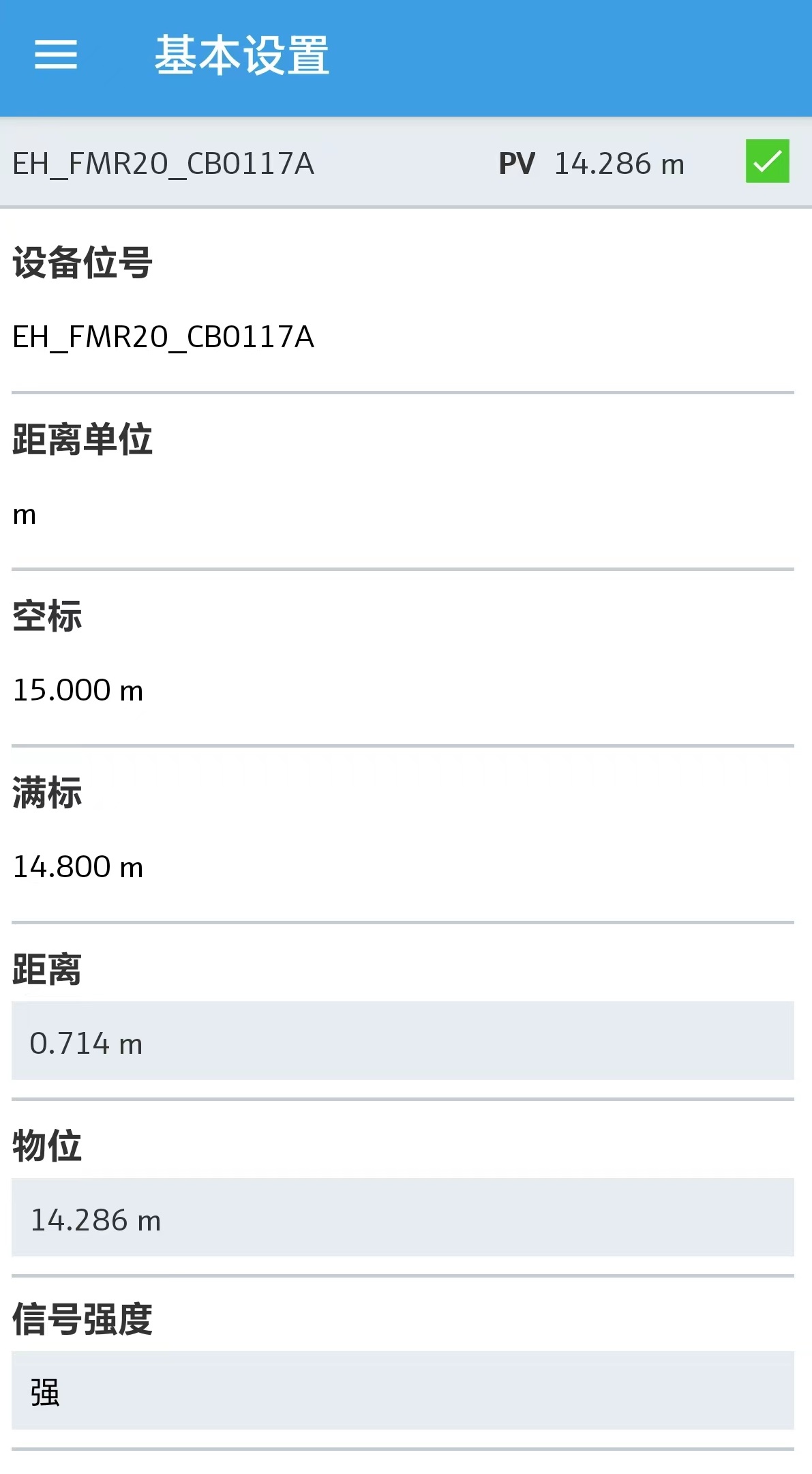
After logging in, go to "Settings" > "Basic Settings" to configure the following parameters:
- Distance unit: meters, feet, etc.
- Empty calibration (E): tank bottom reference point
- Full calibration (F): maximum measuring range
3.3 Communication Settings
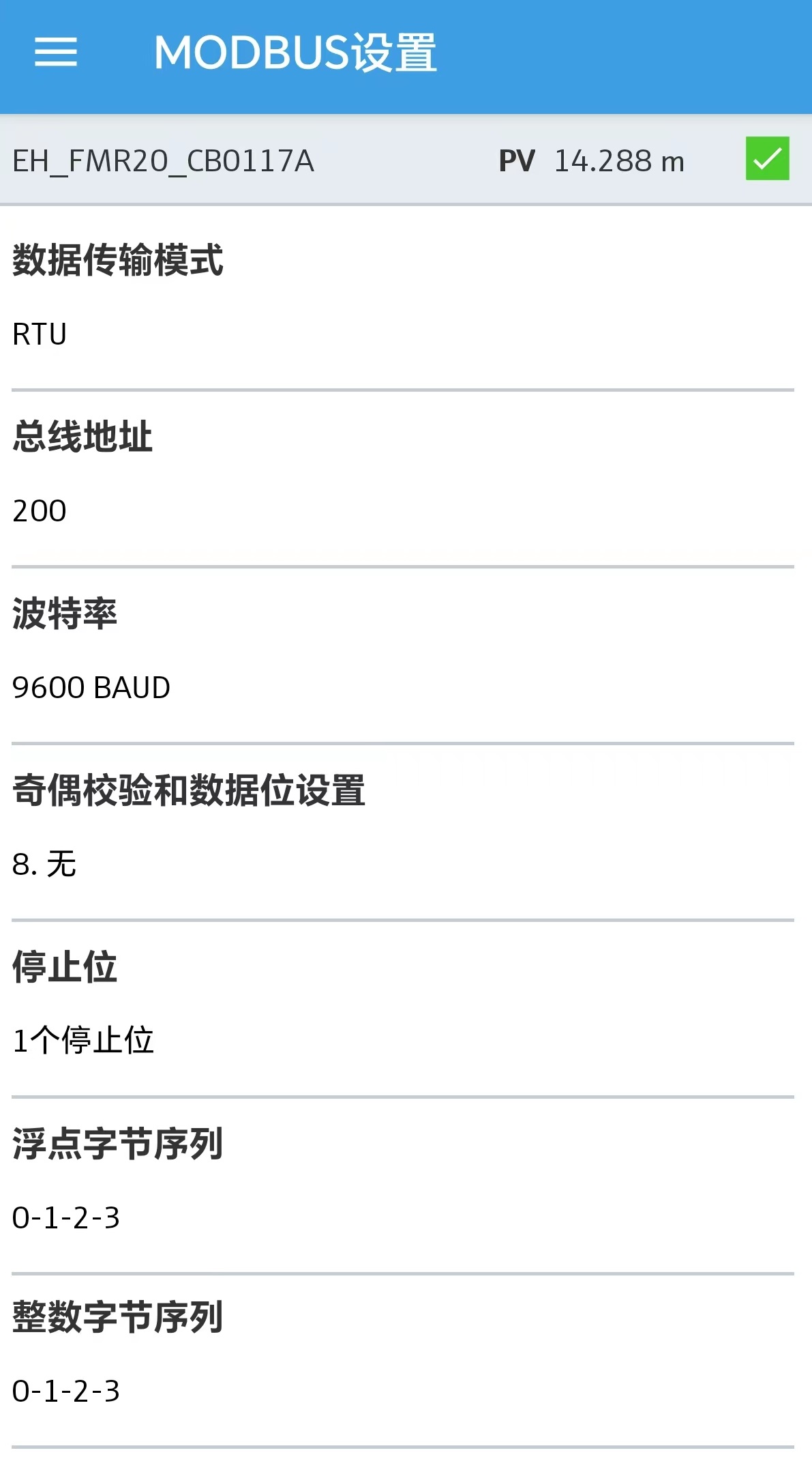
In "Settings" > "Communication", configure the Modbus parameters, including baud rate, data bits, parity, stop bits, and slave address. After setting, close Smartblue and Bluetooth, and prepare to connect to the computer via RS485.
4. Modbus Register Information
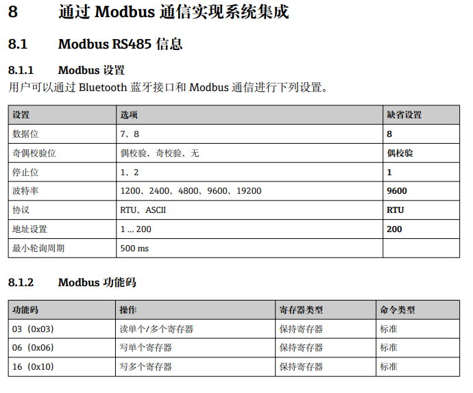
4.1 Register Types
According to Section 8.1.2 of the manual, the Modbus registers of FMR20 are all Holding Registers, function code 03.
4.2 Register Address Definitions
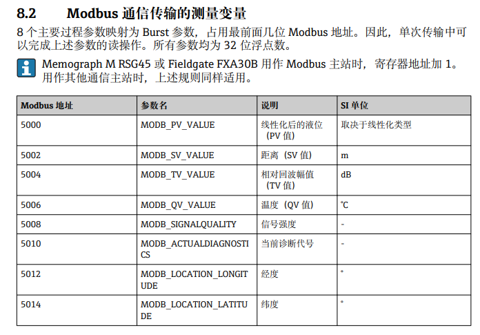
Please refer to the manual for Modbus address definitions. Common registers are shown in the following table:
| Register Address | Data Type | Description |
|---|---|---|
| 0x0000 | Float | Level value |
| 0x0002 | Float | Distance value |
| 0x0004 | Float | Temperature value |
5. Computer Connection and Reading
5.1 Confirming the Port
After connecting to the computer via RS485 to USB, open "Device Manager" > "Ports" and confirm the assigned COM port number (e.g., COM6). An incorrect port number will prevent communication.

5.2 Setting Communication Parameters
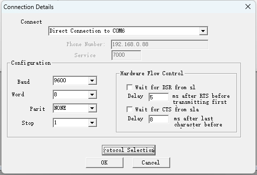
Open the Modbus debugging software, click "Connection" > "Connect", and configure according to the following parameters:
- Port: COM6
- Baud rate: 9600
- Data bits: 8
- Parity: None
- Stop bits: 1
These parameters must match the Modbus parameters set in Smartblue.
5.3 Reading Data
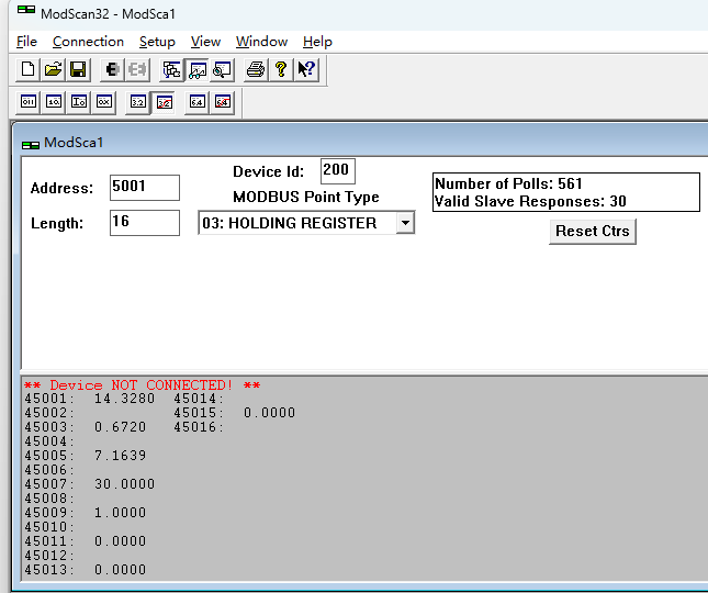
After successful connection, read data according to the register addresses. The figure below shows that the read level value is consistent with the data in Smartblue basic settings, verifying normal communication.
6. Summary
Through the above steps, you can successfully complete RS485 Modbus reading of FMR20. Key points include: correct wiring, configuring communication parameters in Smartblue, confirming the computer COM port, and matching Modbus parameters. If communication fails, please first check the port number and parameter consistency.