1. Wiring Guide
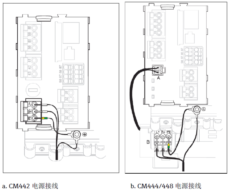
1.1 CM44x Power Wiring
Correct power wiring is the foundation for ensuring stable operation of the transmitter. Please connect the power cables according to the following diagram, paying attention to distinguishing the live wire, neutral wire, and ground wire.
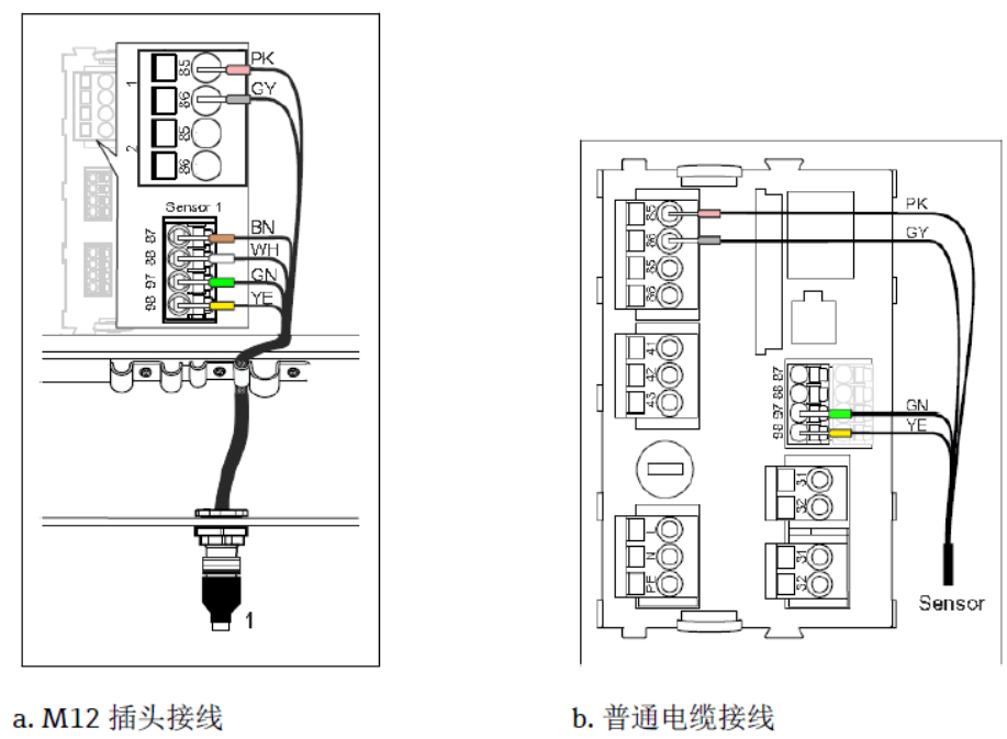
1.2 CM44x to Sensor Wiring
When connecting the CAS40D ion selective electrode to the CM44x transmitter, ensure that the terminal connections correspond correctly. Refer to the following diagram to complete the sensor wiring and avoid signal interference.
2. Transmitter Setup
2.1 Buttons and Interface Description
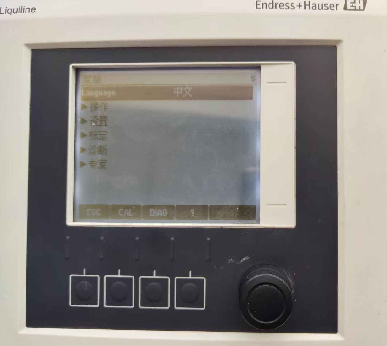
The CM444, CM448, and CM442 have identical appearances; only the number of transmitter channels differs. Here, the CM442 is used as an example to explain button operations. After power-on, the instrument display interface is shown in the following figure, including 4 buttons and 1 knob.
- Knob: Can be rotated left and right to adjust parameters.
- Confirm button: Located in the center of the knob; press to enter the system menu.
2.2 Range Setting
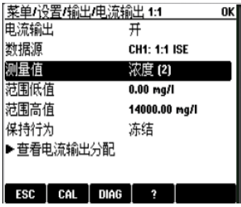
Under the "Menu/Setup/Output settings/Current output x: x" menu, select the correct data source and measured value, and set the range low value and range high value.
2.3 Measurement Compensation Setting
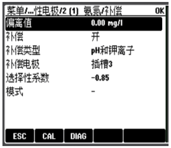
Under the "Menu/Setup/Input/CHx:x:x ISE/Ammonium/Compensation" menu, enable the compensation function and set the compensation type to pH and potassium ion. The selectivity coefficient usually does not need to be changed.
2.4 Air Purge Setting
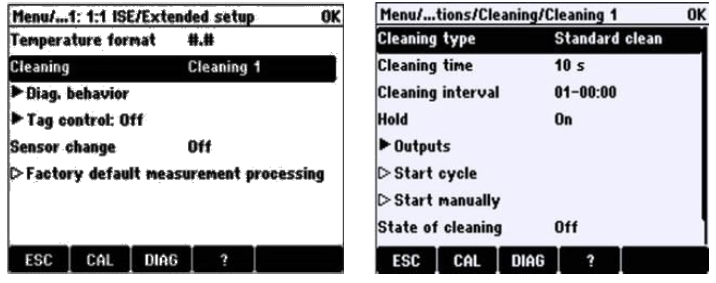
Under the "Menu/Setup/Input/CHx:x:X ISE/Extended setup" menu, bind cleaning to the cleaning program. Then, under the "Menu/Setup/Additional functions/Cleaning" menu, set the cleaning cycle and cleaning time. Once the cycle is started, air purging will begin automatically.
2.5 Transmitter and Sensor Reset
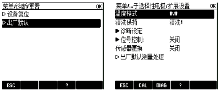
Transmitter reset: Under the "Menu/Diagnostics/Reset" menu, select "Factory default". Sensor reset: Under the "Menu/Setup/Input/CHx:x:X ISE/Extended setup" menu, select "Factory default measuring processing".
3. Calibration Process
For ISE sensors, the pH electrode and the ISE electrode need to be calibrated separately.
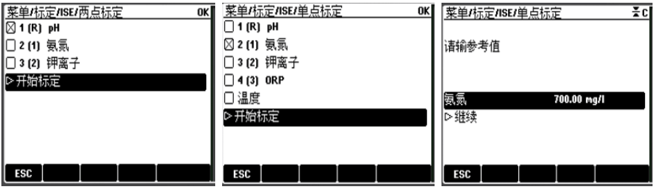
- pH calibration: Use pH standard solution. Under the "Menu/Calibration/ISE/Two-point calibration" menu, select pH and perform calibration.
- ISE single-point calibration: Take 2 L of on-site water sample and obtain the reference value through laboratory testing. Add 1 mL of ammonium/nitrate standard solution provided by E+H to the water sample. The actual reference value should be: laboratory test value + 7 mg/L. Under the "Menu/Calibration/ISE/Single-point calibration" menu, select ammonium/nitrate, enter the reference value, and perform single-point calibration.
4. Maintenance and Care
4.1 Maintenance Cycle
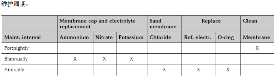
Clean the sensor regularly according to on-site contamination conditions. It is recommended to replace the membrane cap and electrolyte for the ISE electrode (including ammonium/nitrate and potassium ion) every six months; replace the pH reference electrode and chloride ion electrode membrane cap annually. Calibrate the electrode when necessary according to on-site conditions. See the table below for detailed maintenance cycles.
4.2 Maintenance Kit Contents and Replacement Method
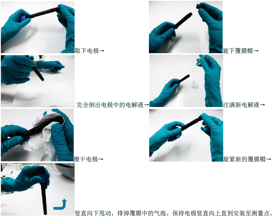
The electrode maintenance kit includes: 2 membrane caps for ammonium/nitrate and potassium ion electrodes, 1 membrane cap for the chloride ion electrode, and one bottle of electrolyte. The method for replacing the ISE electrode membrane and electrolyte is as follows:
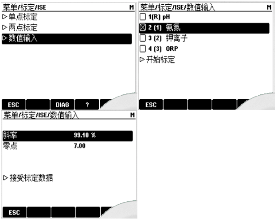
Note: The ISE electrode maintenance kit contains a calibration certificate corresponding to the membrane. After replacing the membrane, the slope on the calibration certificate must be entered into the transmitter calibration information menu, and then a one-point calibration must be performed.
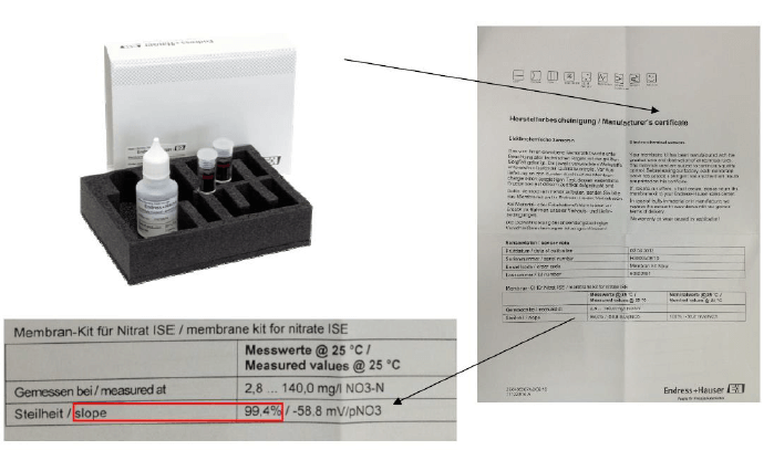
4.3 Method for Entering Slope
For the specific operation of entering the slope, please refer to the following figure.