
RSG35 Universal Data Manager: Electrical Connection and Operation Guide
The RSG35 universal data manager is widely used in the field of industrial automation. Its correct electrical connection and standardized operation are key to ensuring stable device operation. Based on official technical documentation, this article systematically summarizes the wiring requirements, terminal assignment, supply voltage, relays, digital inputs, analog inputs, and front panel operation methods of the RSG35 for reference by engineering technicians and procurement personnel.
1. Electrical Connection
1.1 Wiring Requirements
To ensure the safety of equipment and personnel, the electrical connection of the RSG35 must strictly comply with the following regulations:
- All connections to the device must be made with the power disconnected.
- It is prohibited to connect safety extra-low voltage and hazardous voltage circuits together to the relay.
- Except for the relay and supply voltage circuits, only limited-energy circuits complying with the EC/EN 61010-1 standard may be connected.
- Before making other electrical connections, a ground connection must be established.
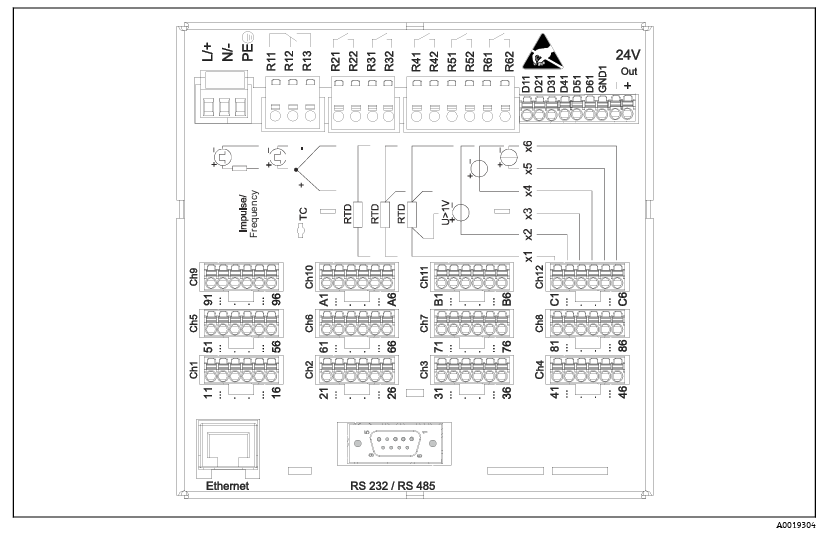
1.2 Diagram of Terminal Assignment on the Rear of the Device
The terminal assignment on the rear of the device is shown in the figure below. Please connect each line correctly according to the diagram.
1.3 RSG35 Instrument Supply Voltage
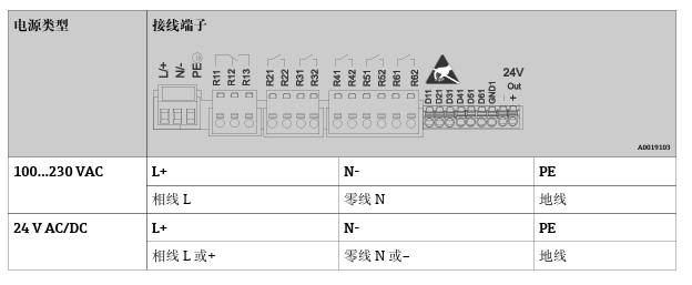
The supply voltage wiring method of the RSG35 is shown in the figure below. Please ensure that the supply voltage is within the specified range of the device.
1.4 Relay
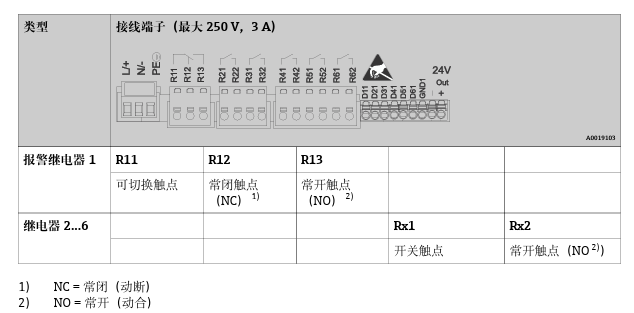
The relay terminal assignment is shown in the figure below. Please note the safety requirements for relay connection.
1.5 Digital Inputs; Auxiliary Voltage Output
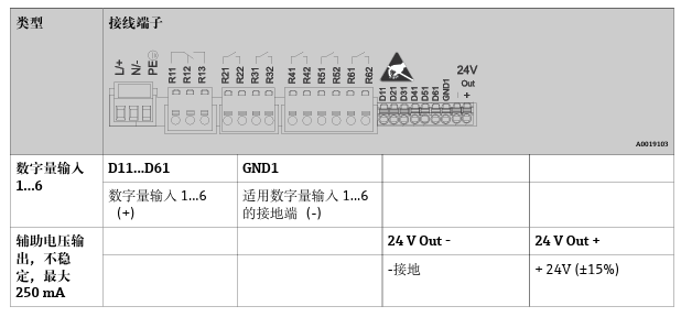
The wiring method for digital inputs and auxiliary voltage output is shown in the figure below.
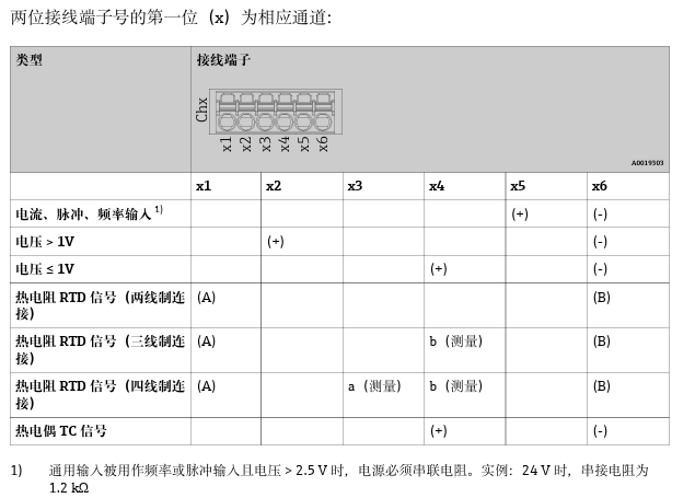
1.6 Analog Inputs
The wiring method for analog inputs is shown in the figure below. Please connect correctly according to the signal type.
2. Operation Method
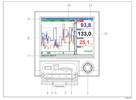
2.1 Diagram of the Device Front Panel with the Panel Opened
The layout of the device front panel is shown in the figure below. The functions of each component are described as follows.
2.2 Front Panel Component Function Description
The following are the components and operation instructions on the front panel:
- Jog/shuttle knob: Used for fast forward/slow reverse and press operation/hold function.
- In display mode: Rotating the knob switches between different signal groups; pressing the knob displays the main menu.
- In setup mode or selection menus: Rotating counterclockwise moves the item or cursor up or left and changes parameters; rotating clockwise moves the item or cursor down or right and changes parameters.
- Short press (< 2 s): Selects the highlighted function parameter and confirms parameter changes (press Enter).
- View online help: Long press the jog/shuttle knob (> 3 s) to display information about the selected function parameter. Press and hold “Back” in the jog/shuttle knob (> 3 s) to exit the menu immediately, and the device switches to display mode.
- LED indicator on the SD card slot: When the device reads from or writes to the SD card, the orange LED indicator lights up. When the LED indicator is on, do not remove the SD card! Otherwise, there is a risk of data loss!
- SD card slot: Used to insert an SD card.
- USB B “slave slot”: For example, connect to a personal computer or laptop.
- Green LED indicator: Lights up to indicate power is on.
- USB A “host slot”: For example, connect a USB flash drive or external keyboard.
- Display mode: Alternately displays the status of analog or digital inputs in the corresponding channel color (for example, setting the scaling range). In setup mode: Different information can be displayed depending on the display type.
- Display mode: Displays the measured value window (for example, curve display). In setup mode: Displays the operation menu.
- Display mode: Current group name, analysis type. Setup mode: Current operation item name (dialog title).
- Display mode: Displays the current date/time.
- Display mode: Alternately displays the percentage of space used on the SD card or USB flash drive. At the same time, alternately displays status icons and storage information (refer to the table below). In setup mode: Displays the current “direct access” operation password.
- Display mode: Displays the current measured value and fault/alarm status.
2.3 Status Icons and Storage Information
The following table lists possible status icons and their meanings in display mode:
| Status Icon | Meaning |
|---|---|
| (Example icon) | SD card inserted and working normally |
| (Example icon) | USB flash drive connected |
| (Example icon) | Data storage in progress |
| (Example icon) | Fault or alarm |
Note: For specific icons, please refer to the device display or the complete manual.