
FMX21 Level Transmitter Working Principle
The FMX21 uses a ceramic sensor as its core measuring element and features a non-oil-filled (dry) design. Process pressure acts directly on the robust ceramic process isolating diaphragm without the need for fill fluid to transmit pressure, avoiding the leakage and temperature drift issues that can occur with oil-filled sensors.
A pressure compensation tube transmits atmospheric pressure changes to the back of the ceramic diaphragm for compensation, ensuring that the measured value reflects only the hydrostatic pressure of the medium. Diaphragm deformation produces a capacitance change proportional to pressure. Electrodes in the ceramic carrier detect this change, and the electronics convert it into a standard signal linearly related to the level.
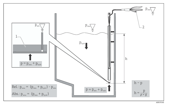
Labels in the figure: 1-ceramic sensor, 2-pressure compensation tube, h-level height, P total pressure = atmospheric pressure + hydrostatic pressure, ρ-medium density, g-gravitational acceleration, Phydr.-hydrostatic pressure, Patm-atmospheric pressure, Psens-pressure value displayed by the sensor.
FMX21 Wiring and Connected Devices
The FMX21 can be used together with a PT100 resistance thermometer to achieve simultaneous level and temperature measurement. Correct wiring is a prerequisite for ensuring measurement accuracy and equipment safety.
FMX21+PT100 Wiring Diagram
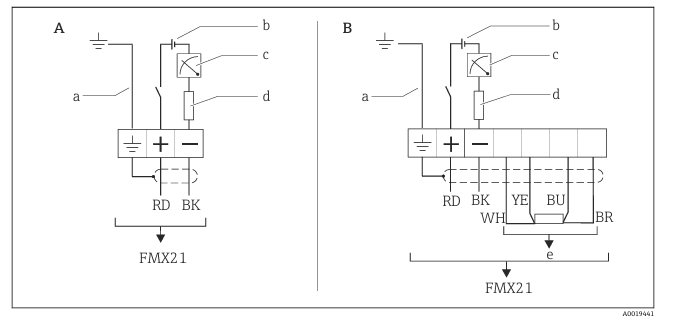
Labels in the figure: A-instrument, B-instrument+Pt100 (non-hazardous area), a-not applicable to instruments with an outer diameter of 29 mm (1.14 in), b-10.5…30 VDC (hazardous area), 10.5…35 VDC, c-4…20 mA, d-resistor (RL), e-Pt100.
Wiring Color Definitions
- RD (red): power supply positive +
- BK (black): power supply negative -
- Yellow-green: ground wire
Commissioning Key Points and Parameter Description
When commissioning the FMX21, attention must be paid to matching the supply voltage and load resistance, especially when used in hazardous areas. The following is a comparison of key parameters:
| Parameter | Non-hazardous area | Hazardous area |
|---|---|---|
| Supply voltage | 10.5…35 VDC | 10.5…30 VDC |
| Output signal | 4…20 mA | 4…20 mA |
| Load resistance | Depends on supply voltage | Depends on supply voltage |
Commissioning steps:
- Confirm that the supply voltage is within the permissible range; in hazardous areas, it must not exceed 30 VDC.
- Connect the power supply and ground wires correctly according to color, and ensure the PT100 wiring is secure.
- Check whether the load resistance meets the loop requirements to avoid signal distortion.
- After power-on, observe whether the output current responds linearly to changes in level.
Key conclusion: The FMX21's ceramic sensor has an oil-free design, making it suitable for hygienic and high-reliability applications; when wiring, be sure to distinguish between hazardous and non-hazardous voltage ranges to ensure safety and compliance.