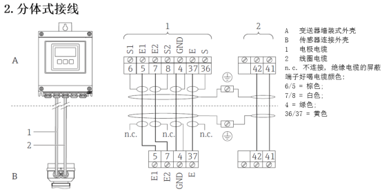
Promag 400 Electromagnetic Flowmeter Wiring Overview
Promag 400 is a high-performance electromagnetic flowmeter launched by Endress+Hauser, widely used in industrial process measurement. Correct wiring is the foundation for ensuring its measurement accuracy and long-term stable operation.
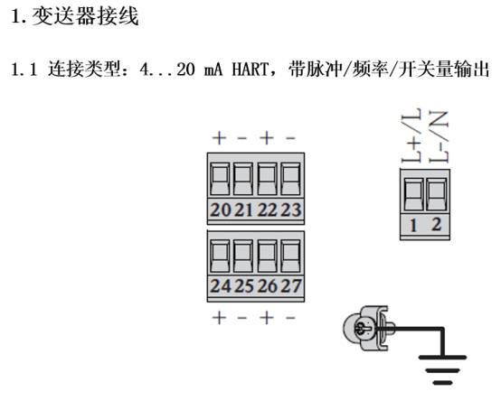
This article, combined with wiring diagrams, introduces the wiring method, terminal definitions, and precautions of Promag 400 step by step, for the reference of engineering technicians and procurement personnel.
Preparation Before Wiring
Tools and Materials Preparation
- Phillips screwdriver, wire stripper, crimping tool
- Multimeter (for continuity testing)
- Power cables and signal cables that meet specifications
- Cable sealing joints (cable glands)
- Waterproof tape or heat-shrink tubing
Safety Precautions
- Ensure the power supply is disconnected and hang a "Do Not Close" warning sign.
- Confirm that the power supply voltage on the instrument nameplate matches the on-site power supply.
- Avoid excessive bending of cables during wiring to prevent damage to internal wires.
Terminal Definitions and Cable Selection
Terminal Function Description
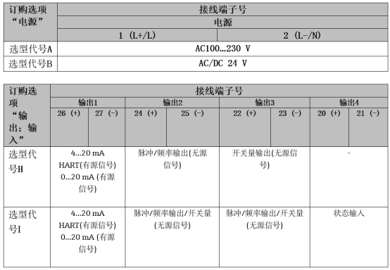
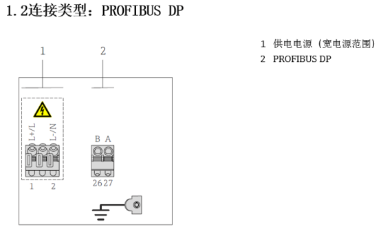
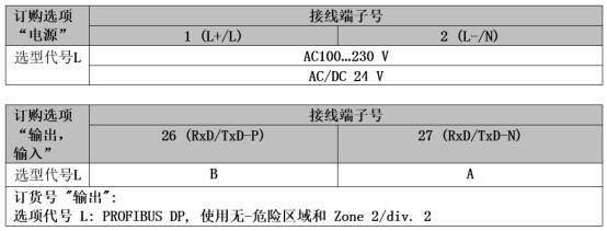
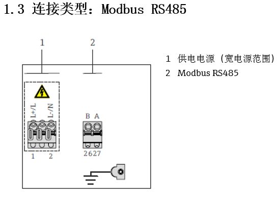
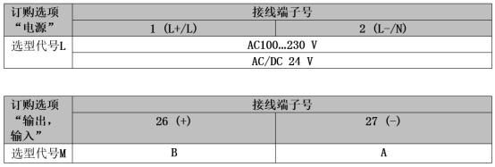
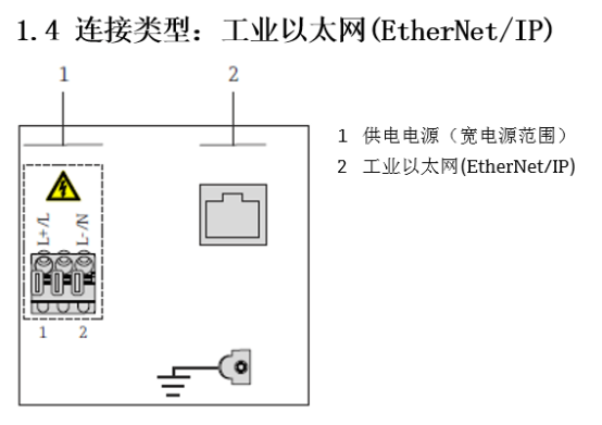
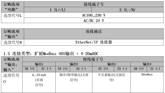
The wiring terminals of the Promag 400 are usually located inside the transmitter electronics compartment. The specific definitions are shown in the following table:
| Terminal Number | Function | Cable Type | Remarks |
|---|---|---|---|
| 1, 2 | Power input (L, N) | Power cable | 85~265 VAC or 24 VDC |
| 3, 4 | Current output (4~20 mA) | Shielded twisted pair | Active/passive selectable |
| 5, 6 | Pulse/frequency output | Shielded twisted pair | For flow totalization or alarm |
| 7, 8 | Digital input/output | Shielded twisted pair | Configurable as status input or output |
| 9, 10 | Grounding | Ground wire | Must be reliably grounded |
Cable Selection Recommendations
- Power cable: Select the cross-sectional area based on supply voltage and distance, generally ≥1.0 mm².
- Signal cable: Must use shielded twisted pair, with the shield grounded at one end to avoid interference.
- The cable outer diameter should match the cable gland to ensure the sealing level.
Detailed Wiring Steps
Step 1: Open the Transmitter Housing
- Loosen the fastening screws on the transmitter cover.
- Carefully remove the housing cover, taking care not to damage the sealing ring.
- Place the housing cover in a clean and safe place.
Step 2: Introduce the Cable
- Select the appropriate cable gland according to the cable outer diameter and install it on the transmitter cable entry.
- Strip the cable jacket about 100 mm to expose the core wires.
- Strip about 8 mm of insulation from the end of the core wires and crimp cold-pressed terminals (if needed).
Step 3: Connect the Power Cable
- Connect the power wires (L, N) to terminals 1 and 2 respectively.
- Ensure the connection is firm and there is no exposed copper wire.
- For DC power supply, pay attention to the correspondence between positive and negative poles and terminals.
Step 4: Connect the Signal Cable
- Connect the 4~20 mA output wires to terminals 3 (+) and 4 (-).
- Connect the pulse/frequency output wires to terminals 5 (+) and 6 (-).
- Connect the digital input/output wires to terminals 7 and 8.
- Connect the shielding layer of all signal cables to grounding terminals 9 or 10.
Step 5: Grounding Connection
- Use a ground wire to connect terminal 9 or 10 to a reliable grounding body.
- The grounding resistance should be less than 10 Ω.
- Ensure the ground wire is as short and thick as possible.
Step 6: Inspection and Closing the Cover
- Check that all wiring is correct and firm.
- Use a multimeter to check that there is no short circuit at the power input end.
- After confirming everything is correct, replace the housing cover and tighten the screws.
- Restore power and observe whether the instrument starts normally.
Wiring Precautions
- The power supply voltage must match the nameplate, otherwise the instrument may be damaged.
- Signal cables must be shielded, and the shield should be grounded at one end to avoid ground loop interference.
- Grounding must be reliable; poor grounding can cause measurement fluctuations or errors.
- Cable sealing: Ensure the cable gland is tightened to prevent moisture from entering.
- Avoid parallel routing with power cables. If unavoidable, maintain a distance of at least 30 cm.
Common Problems and Troubleshooting
No Display on the Instrument
- Check whether the power supply is connected and the voltage is normal.
- Check whether terminals 1 and 2 are in good contact.
- Check whether the fuse is blown.
Abnormal Output Signal
- Check whether the signal wires are reversed or short-circuited.
- Check whether the shielding layer is properly grounded.
- Confirm whether the transmitter parameter settings are correct.
Fluctuating Measurement Values
- Check whether the grounding is reliable.
- Check whether the sensor is filled with liquid.
- Eliminate nearby strong electromagnetic interference sources.
Summary
Although the wiring of the Promag 400 is not complicated, details determine success. Following the correct steps and precautions can ensure long-term stable operation of the instrument.
It is recommended that wiring be performed by professionals and carefully checked before power-on. If you have any questions, please refer to the official manual or contact technical support.