Promag 400 Electromagnetic Flowmeter Installation Guide
Correct installation of the Promag 400 electromagnetic flowmeter is crucial for measurement accuracy and equipment lifespan. This guide covers key points such as installation location, orientation, straight pipe sections, system pressure, vibration, and adapter pipes to help you standardize installation.
1. Installation Location
Choosing a suitable installation location can avoid measurement errors and equipment damage. The following explains different cases.
Downward Draining Pipe
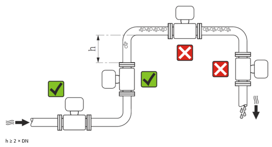
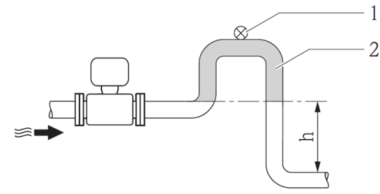
When installing in a vertical downward pipe (height h ≥ 5 m), a siphon or drain valve must be installed downstream of the sensor to prevent suction pressure from damaging the measuring tube liner and to avoid long-term reduction in system accuracy.
Installation in a vertical downward pipe: 1 - drain valve; 2 - siphon; h - length of the vertical downward pipe.
Partially Filled Pipe
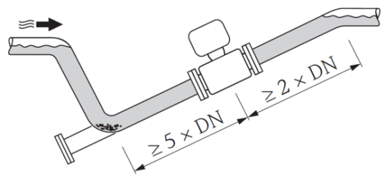
An inclined partially filled pipe requires a drain outlet. The empty pipe detection (EPD) function can detect empty or partially filled pipe conditions, providing additional protection.
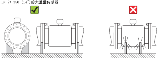
2. Installation Orientation
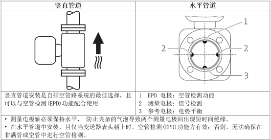
Install according to the arrow direction on the sensor nameplate, ensuring the arrow is consistent with the medium flow direction in the pipe. The optimal installation position should prevent gas and air accumulation in the measuring tube, as well as solid deposition.
3. Upstream and Downstream Straight Pipe Sections
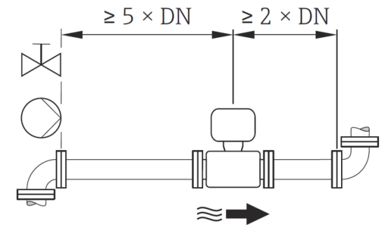
To ensure measurement accuracy, please ensure the following upstream and downstream straight pipe section lengths:
4. System Pressure
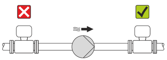
Do not install the sensor on the inlet side of a pump to avoid suction pressure damaging the measuring tube liner. When using piston pumps, diaphragm pumps, or peristaltic pumps, a pulsating flow buffer must be installed.
5. Vibration
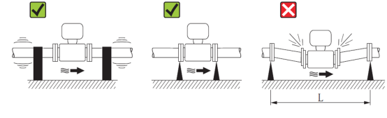
When used in strong vibration environments, please support and secure the pipe and sensor. Measures to avoid equipment vibration (L > 10 m) are shown in the figure below.
6. Adapter Pipes
When the sensor needs to be installed in a large-diameter pipe, an adapter pipe compliant with DIN EN 545 standard (double-flange reducer) can be selected. When measuring fluids with extremely slow flow, the flow velocity can be increased to improve measurement accuracy.
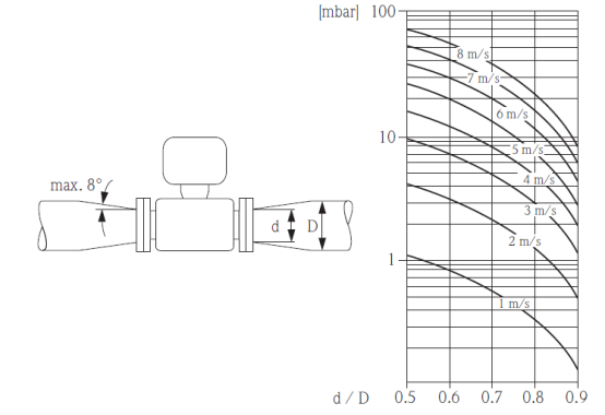
Refer to the figure below to calculate the pressure loss of the system after using reducers and expanders:
- Calculate the diameter ratio d/D.
- Based on the flow velocity (at the downstream of the reducer) and the diameter ratio d/D, refer to the figure below to calculate the pressure loss.