FMU30 Ultrasonic Level Meter Basic Setup Steps
The FMU30 is one of the most widely used level meters on the market, featuring two-wire power supply where the power line and signal line share the same cable. This article provides a detailed introduction to its basic setup process, and the FMU40 ultrasonic level meter is equally applicable. The following steps are intended for engineering and technical personnel as well as procurement personnel, helping you quickly complete instrument commissioning.
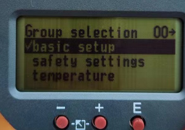
1. Enter the Basic Setup Menu
After power-on, press the E key to enter basic setup. This is the starting point for all parameter configuration.
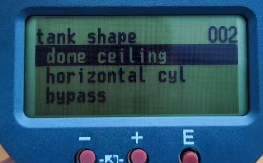
2. Select Tank Shape
Press the E key again to enter the tank shape selection interface. Select the corresponding option according to the actual tank type. Common shapes are as follows:
- A dome ceiling: Dome roof tank
- B horizontal cyl.: Horizontal tank
- C bypass / stilling well / ultrasonic guide pipe: Bypass pipe, stilling well, or ultrasonic guide pipe
- D no ceiling: Open-top tank
- E sphere: Spherical tank
- F flat ceiling: Flat roof tank
Please select according to the actual tank shape at the user's site to ensure measurement accuracy.
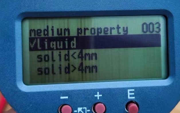
3. Set Medium Properties
After selecting the tank shape, press the E key to enter medium property settings. The selectable types include:
- Liquid
- Solid particles smaller than 4mm
- Solid particles larger than 4mm
Select the corresponding property according to the actual medium in the tank.
4. Set Process Parameters
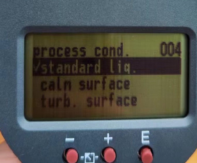
Press the E key to enter Process conditions settings. Usually, the default selection is standard liquids. Brief descriptions of other options are as follows:
- calm surface: Calm liquid surface
- turb. surface: Turbulent liquid surface
- add. agitator: Additional agitator
- fast change: Fast change
- standard solid: Standard solid
- solid dusty: Solid dust
- conveyor belt: Conveyor belt
Select according to the actual working conditions. Generally, standard liquids can be used for liquid measurement.
5. Set Empty Calibration, Full Calibration, and Blocking Distance
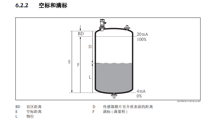
Press the E key to enter empty calibration, full calibration, and blocking distance settings. On-site personnel need to input specific values according to the tank dimensions.
Key relationship: Full calibration (full range) = Empty calibration distance - Blocking distance. Please set the specific parameters according to the actual on-site conditions.
6. Switch Display Mode (Distance/Percentage)
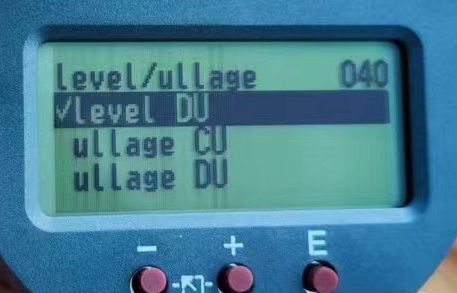
On the display interface, press the E key, then press the ↓ key to find Linearisation, and press the E key to enter. The display options include:
- Level DU: Display actual distance
- Level CU: Display percentage distance
- ullage CU: Display remaining actual distance
- ullage DU: Display remaining percentage distance
Users can select the display mode according to their needs.
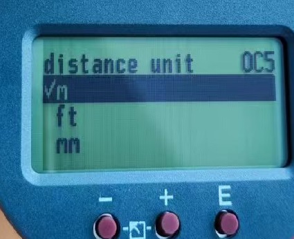
7. Set Length Unit
On the display interface, press the E key, press the ↓ key to find system parameter, then press the E key to enter, and you can select the desired length unit.