
Detailed Explanation of Basic Setup Steps for CM442 Transmitter
Taking the commonly used CM442-3PQ7/0 as an example, this article provides a detailed introduction to the basic setup steps of the CM442 transmitter, including wiring, power-on, language modification, general settings, and current output configuration. It is suitable for reference by engineering and technical personnel and procurement personnel.
1. CM442 Wiring Diagram
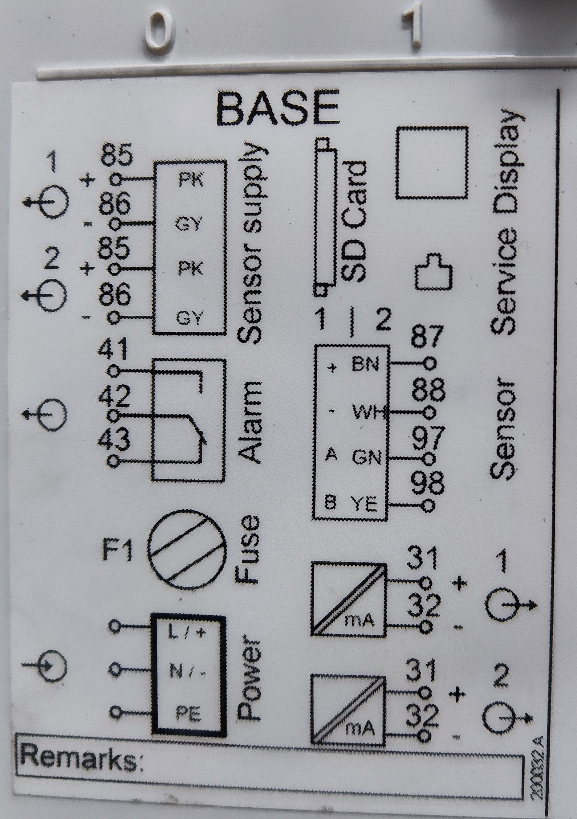
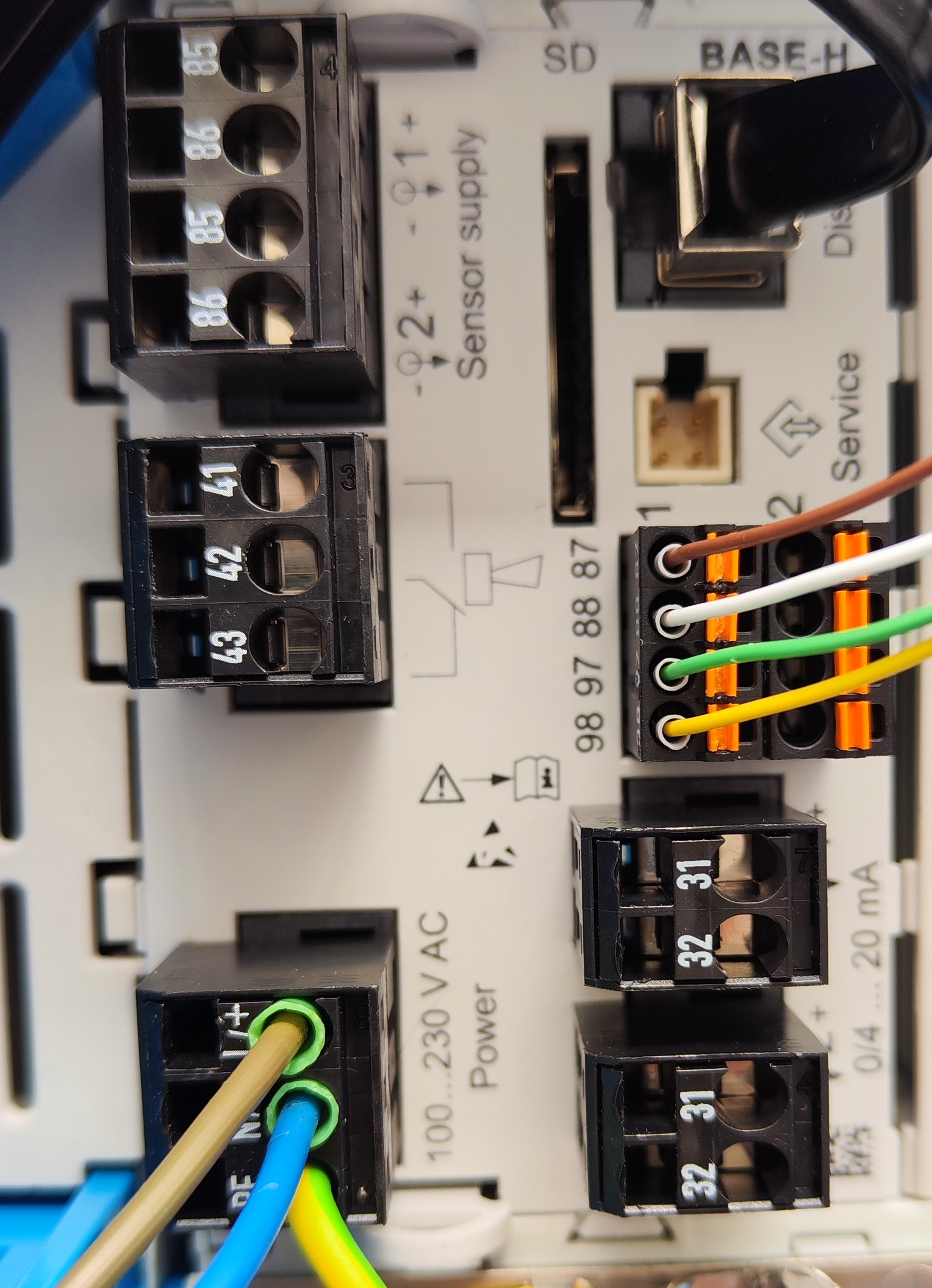
The CM442 mainboard display power supply is 220 V AC. This example uses a CPS glass electrode (digital sensor), without an additional power supply, and uses a CYK10 digital electrode cable. The wiring color correspondence is as follows:
- 87: Brown
- 88: White
- 97: Green
- 98: Yellow
2. Instrument Display Interface After Power-On
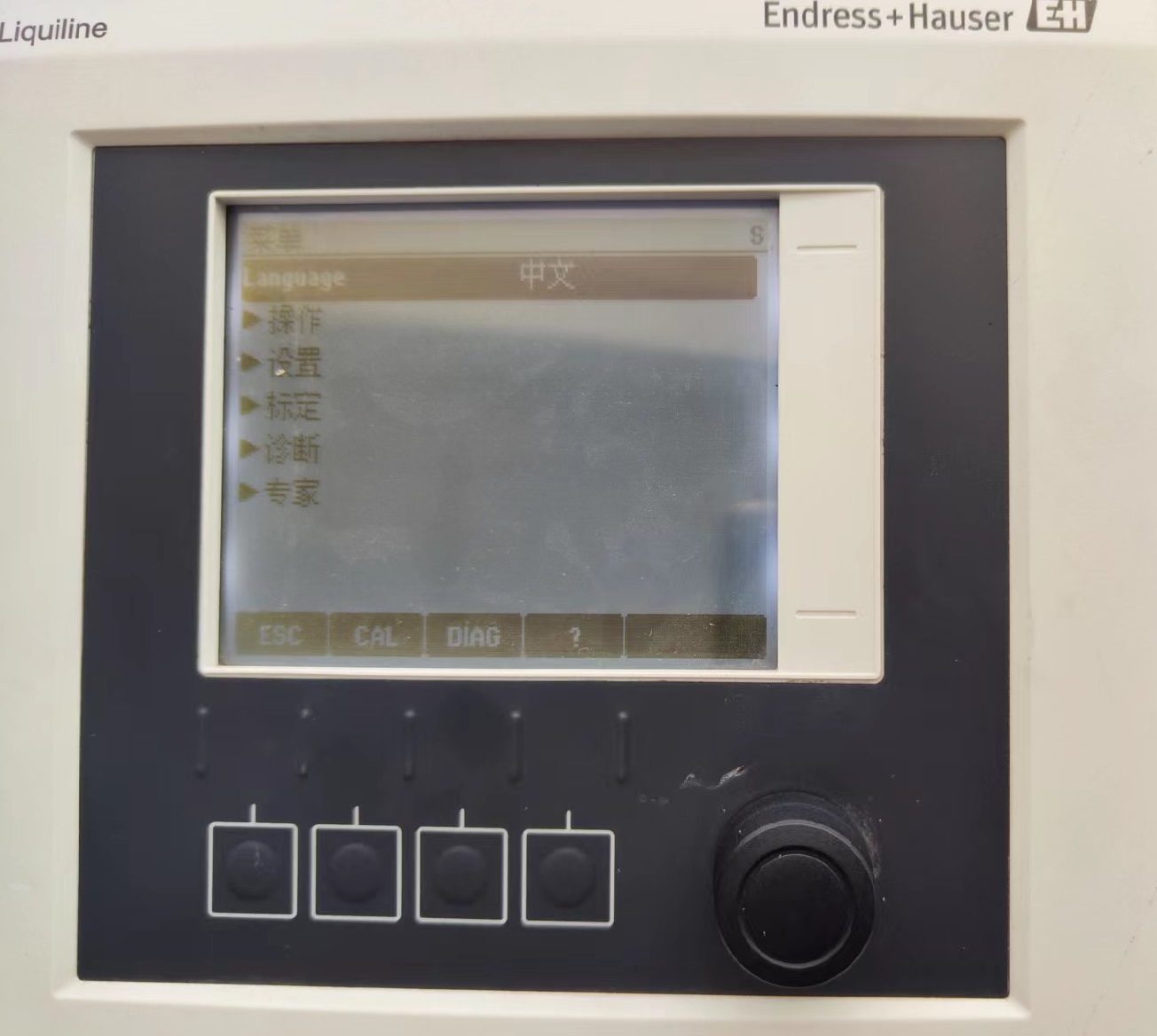
After power-on, the instrument display interface is as shown in the figure below. The interface contains 4 buttons and 1 knob. The knob can be adjusted left and right, and the center of the knob is the confirm key. Pressing the confirm key enters the system menu.
3. Changing the Language
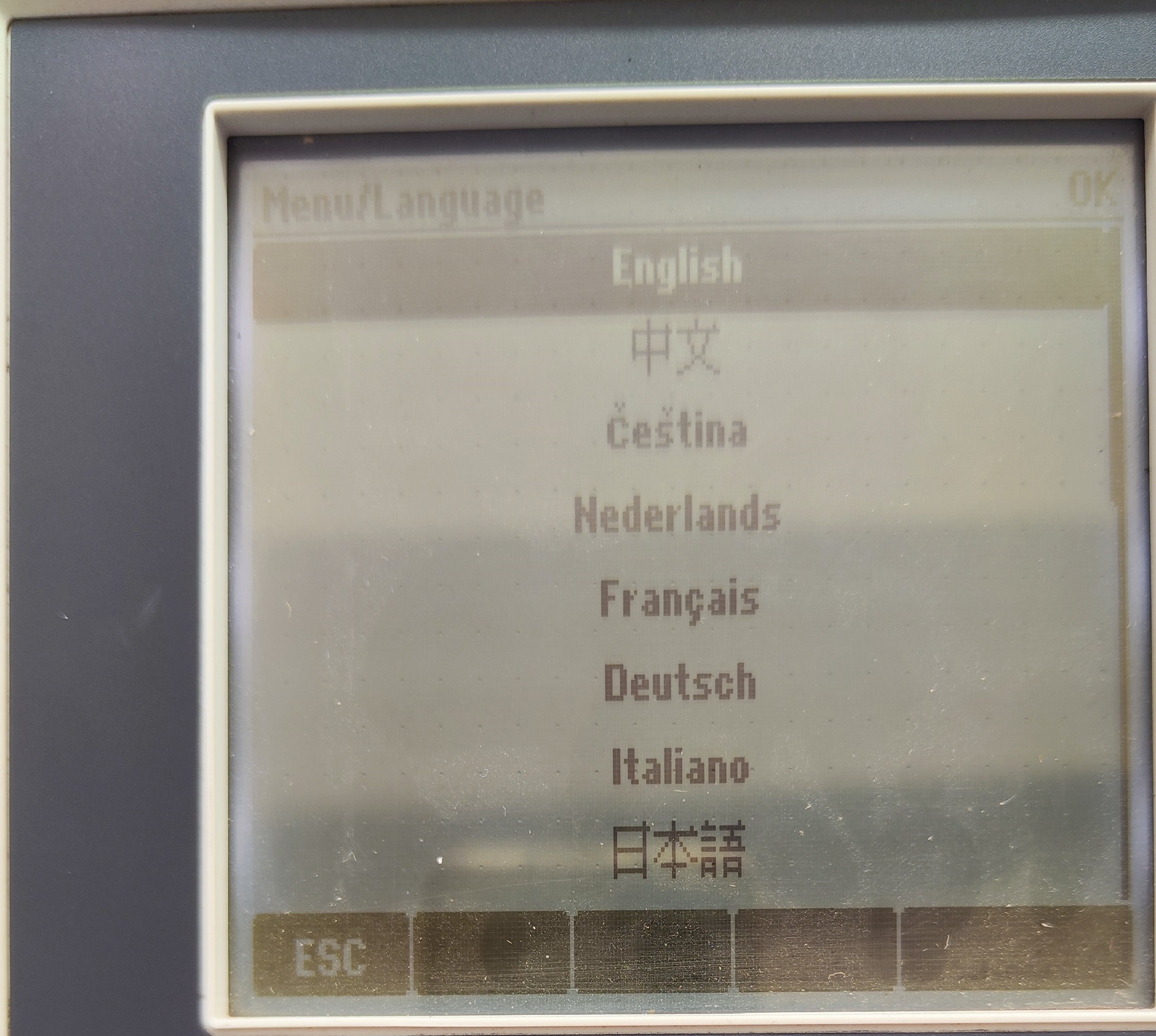
Find the Language option in the menu, and press the center of the knob to change the language displayed as needed by the user. Therefore, when purchasing the CM442, language selection is not mandatory and can be adjusted manually later.
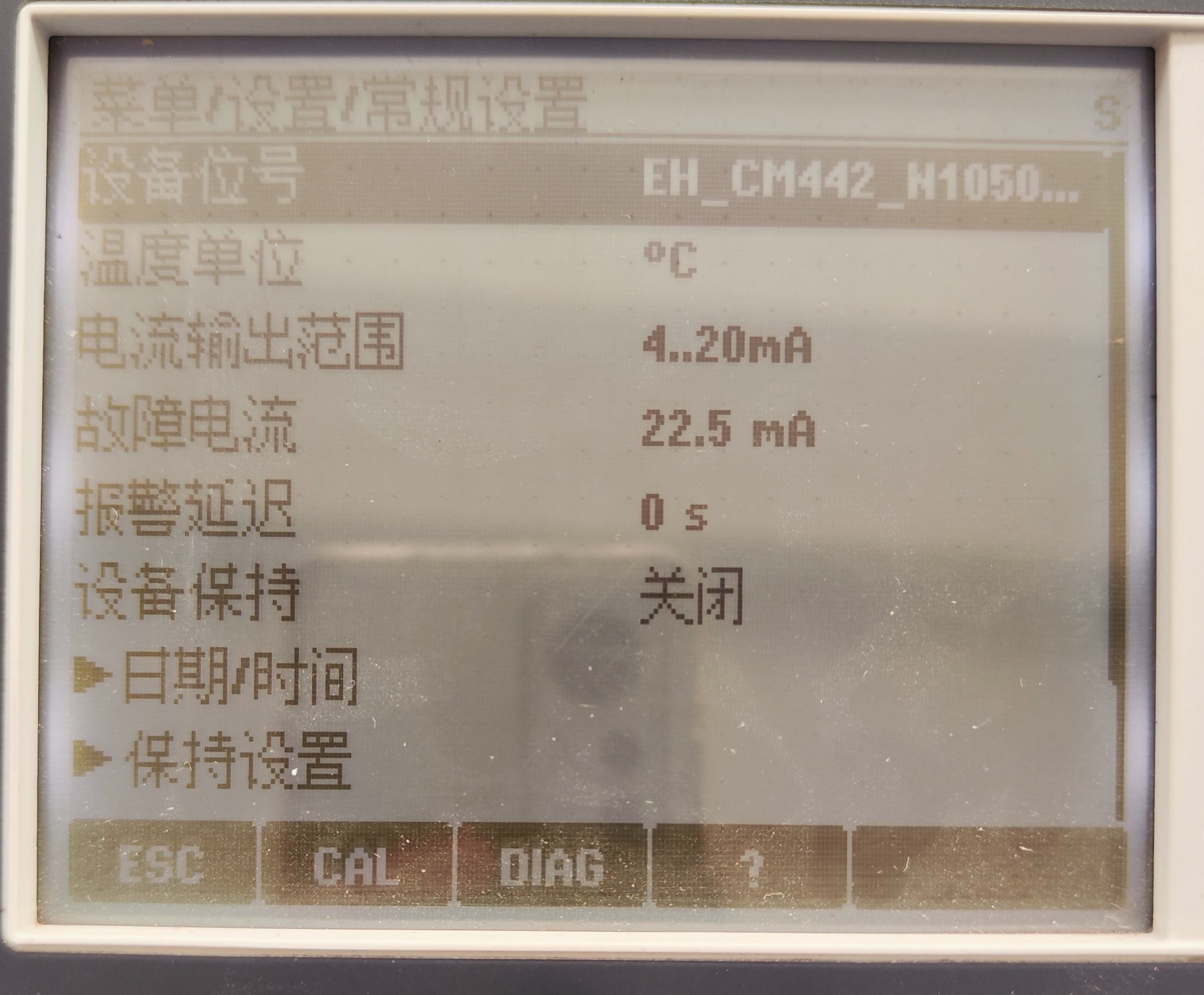
4. General Settings
Find General Settings in the menu interface. Digital sensors have built-in electronic components that store calibration parameters and other information. Once the sensor is successfully connected to the transmitter, the sensor parameters are immediately automatically transmitted to the transmitter for calculating the current measured value. Users can select the temperature unit and current output range according to their needs.
5. Current Output Settings
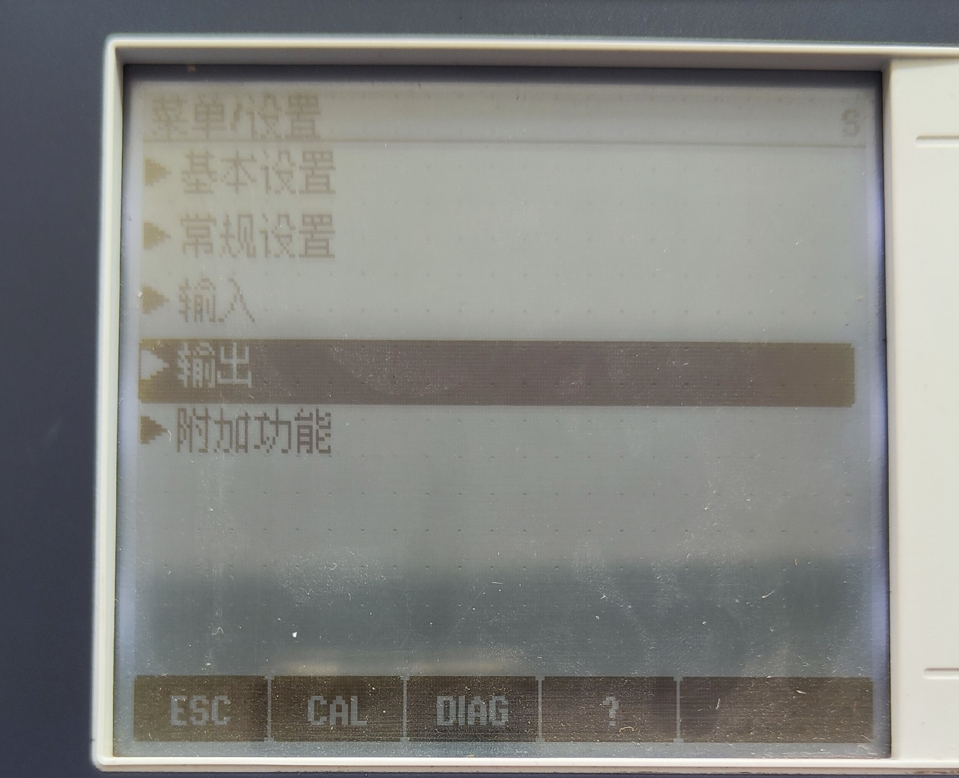
5.1 Entering the Output Interface
Find Settings in the menu interface, press the center of the knob, and enter the output interface.
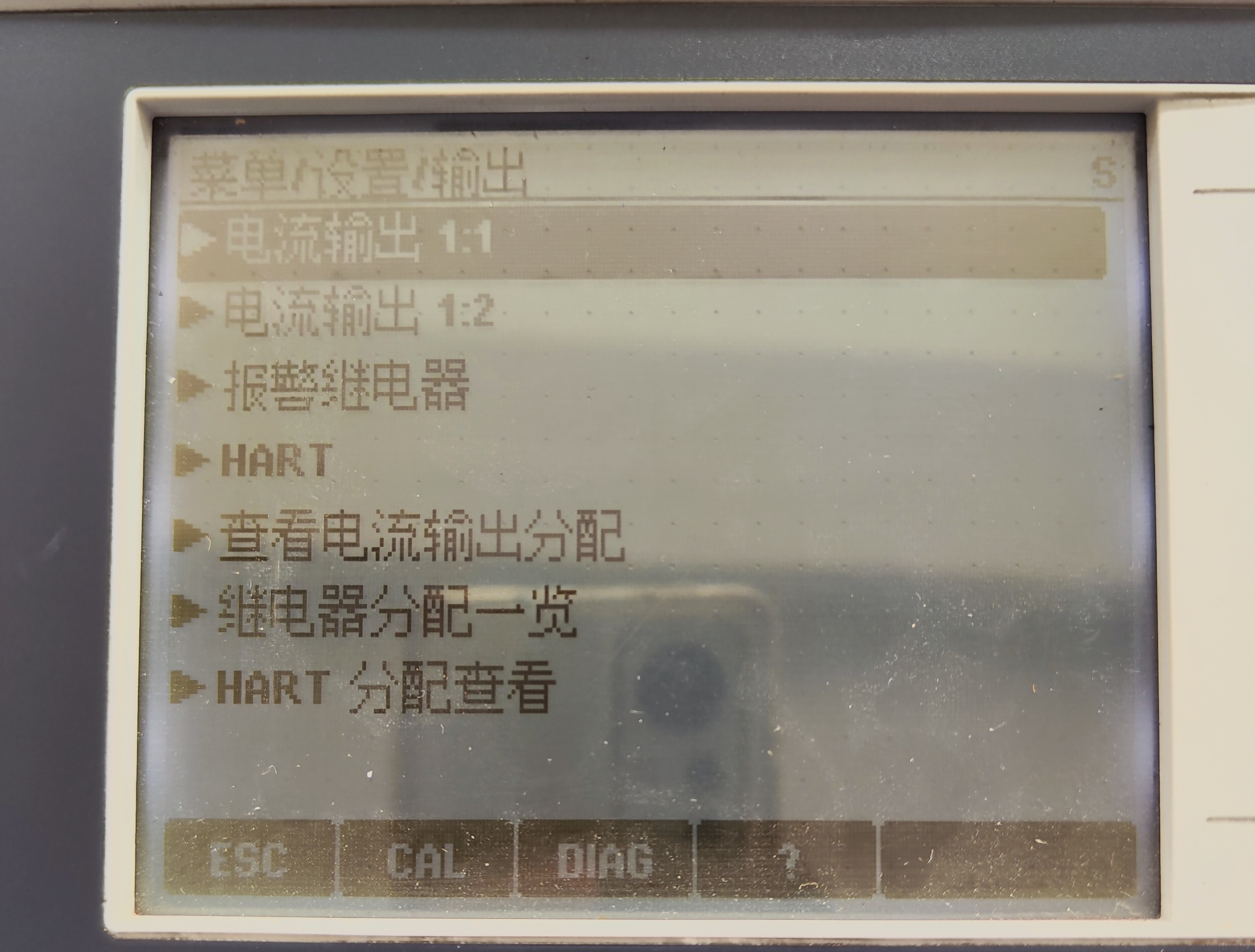
5.2 Selecting the Current Output Channel
The interface displays Current Output 1:1 and Current Output 1:2. Press the center key to enter each respectively.
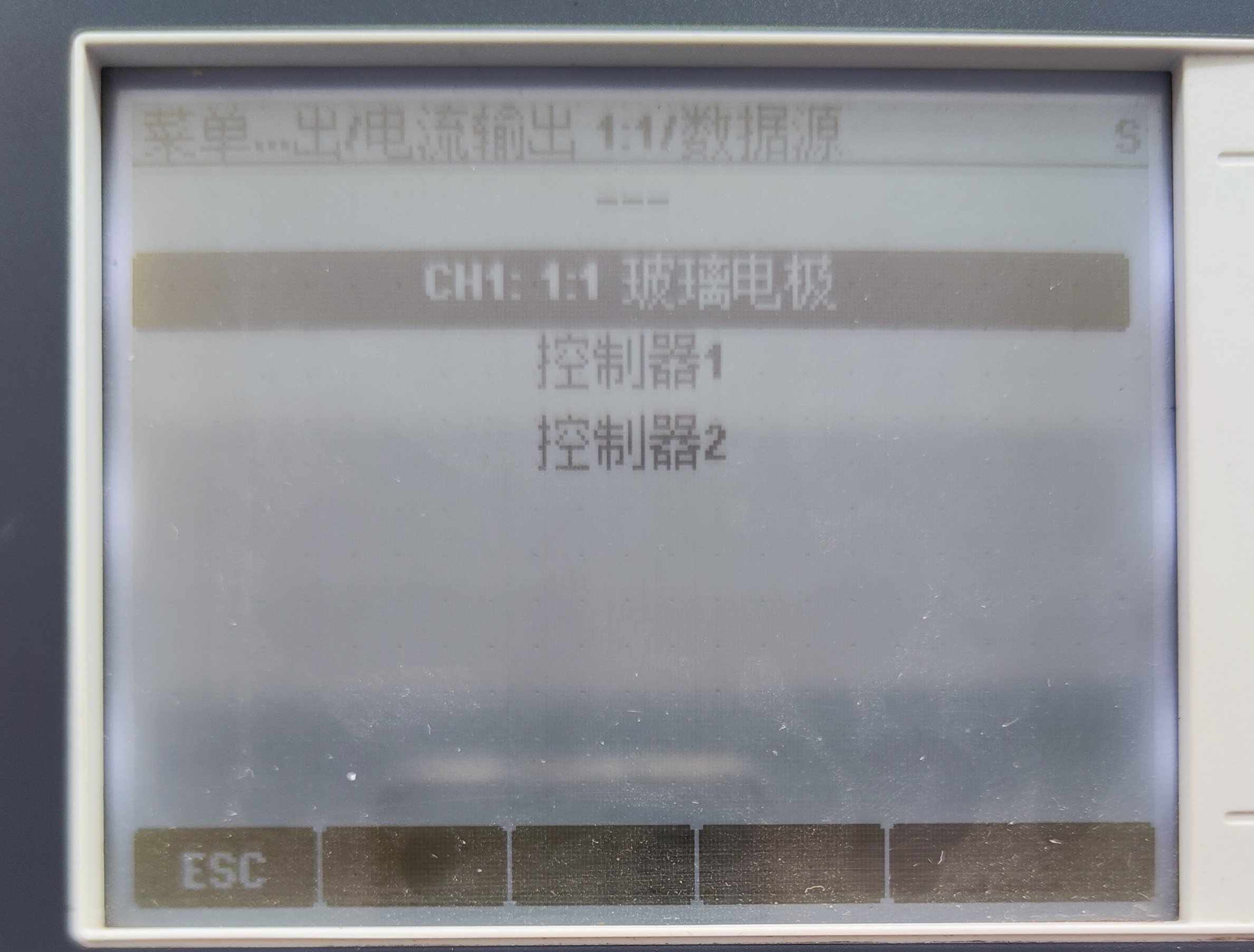
5.3 Setting the Data Source
Use the knob to select Data Source, and press the center key of the instrument.
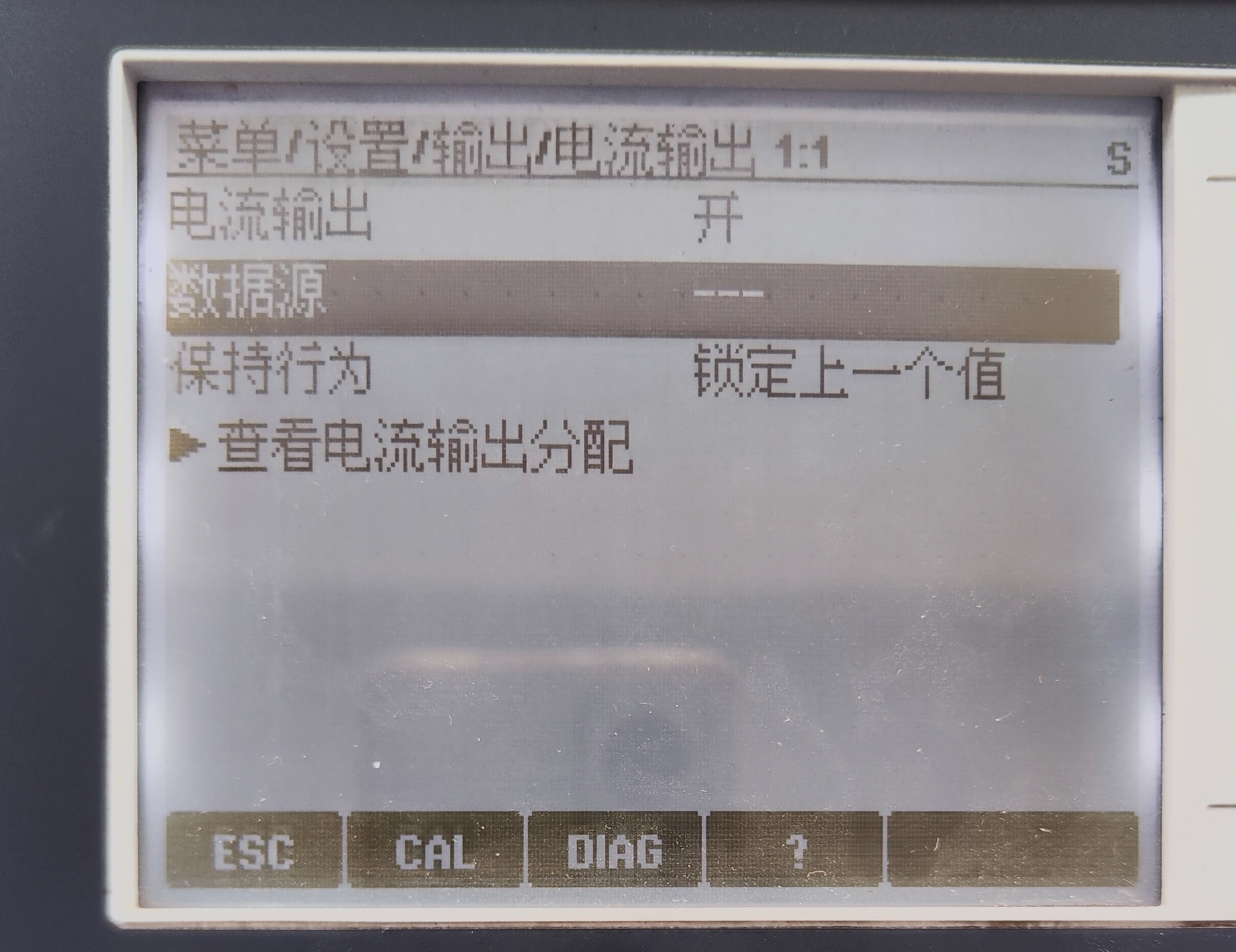
As shown in the figure below, Glass Electrode is selected. Users can select the data source according to different sensors.
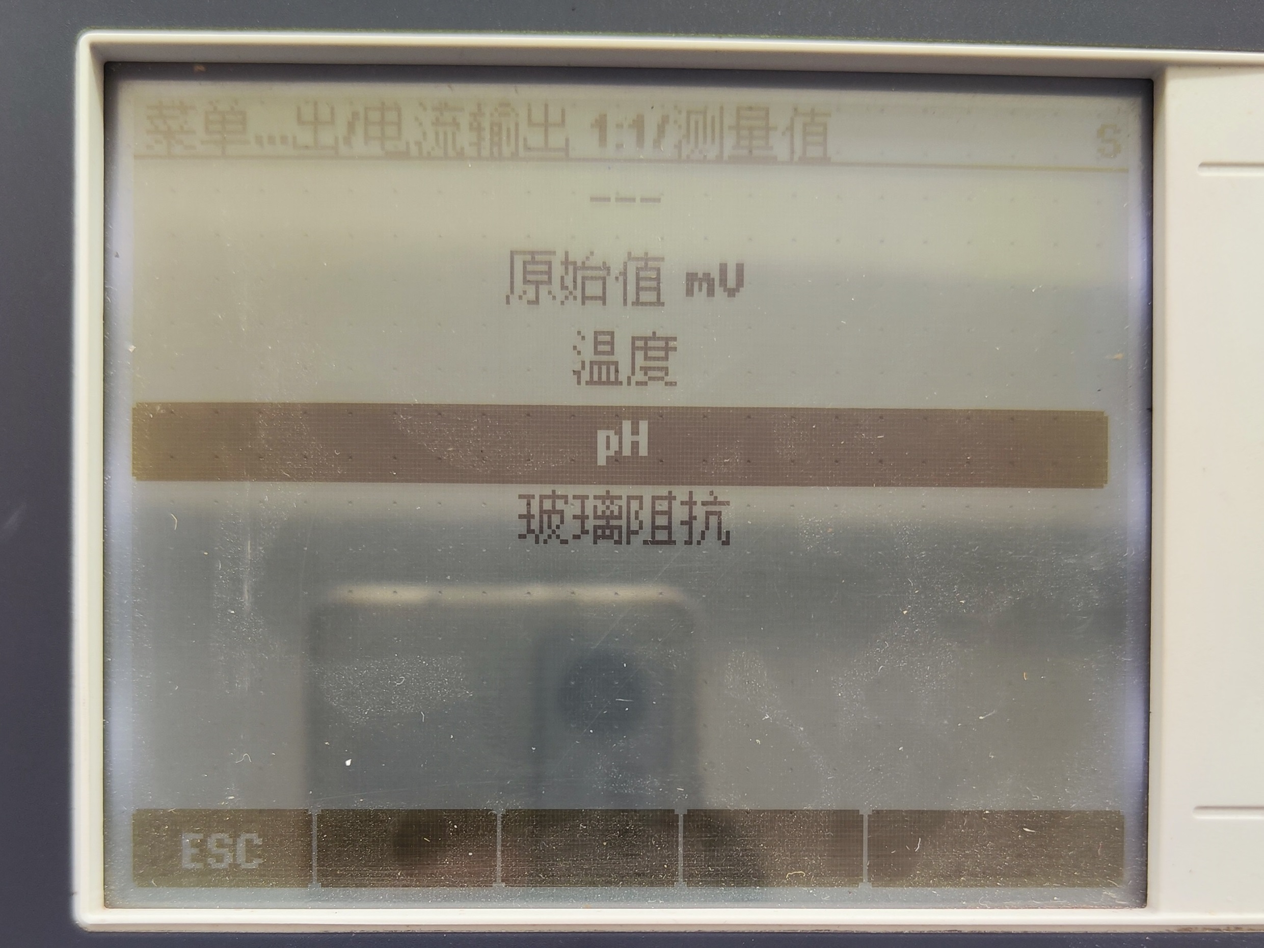
5.4 Selecting the Measured Value
After selecting the data source, the measured value will appear on the display interface. Users can select the required measured value according to their needs. The settings for Current Output 1:2 are basically the same as those for Current Output 1:1, and can be set by referring to the steps for Current Output 1:1.
6. Summary of Key Parameters
| Item | Parameter/Description |
|---|---|
| Supply Voltage | 220 V AC |
| Electrode Type | CPS glass electrode (digital) |
| Cable Model | CYK10 digital electrode cable |
| Wiring Colors | 87 brown, 88 white, 97 green, 98 yellow |
| Language Setting | Can be modified manually; no need to specify at purchase |
| Current Output | Current Output 1:1 and 1:2, can be configured independently |
Through the above steps, the basic setup of the CM442 transmitter can be completed. For further adjustments, please refer to the detailed operation manual.