
CPM253/223 Transmitter and pH/ORP Sensor Wiring Guide
The CPM253/223 transmitter is a commonly used device in industrial pH/ORP measurement. Correct wiring is the key to ensuring accurate measurement and stable system operation. This article introduces the wiring methods for analog sensors and Memosens digital sensors step by step, and explains the key functions.
1. Wiring Steps
1.1 Connecting Analog Sensors
Analog sensors include standard analog sensors, ISFET analog sensors, and glass sensors, and the wiring methods differ slightly. Please follow the steps below:
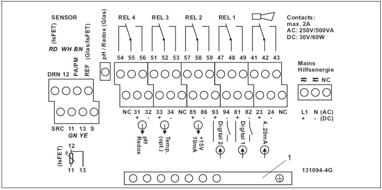
- Affix the corresponding wiring diagram supplied with the unit to the terminal block.
- Connect the green, white, and yellow temperature wires to terminals 11, 12, and 13, respectively.
- For standard analog sensors (using CPK9 cable): the coaxial wire and black shield wire represent the measurement and reference signals, respectively, and are connected to the “pH” and “REF” terminals; the brown equipotential wire is connected to the “PA/PM” terminal.
- For ISFET analog sensors (using CPK12 cable): the coaxial core wire and black shield wire represent the measurement and reference signals, respectively, and are connected to the “SRC” and “REF” terminals; the red wire is connected to the DRN terminal; the brown equipotential wire is connected to the “PA/PM” terminal.
- Connect the outer shield of the glass sensor cable to the “S” terminal; connect the outer shield of the ISFET sensor cable to the PE terminal, and ground the PE terminal.
- Do not connect terminals marked “NC” or unmarked terminals.
- Connect 220VAC power to the L1 and N terminals; connect 24VDC power to the + and - terminals.
- Connect the first current output (pH) to terminals 31 and 32, and the second current output (temperature, optional) to terminals 33 and 34. The current output is an active output.
1.2 Connecting Memosens Digital Sensors
Memosens digital sensors use a four-wire connection, making wiring simpler. Please follow the steps below:
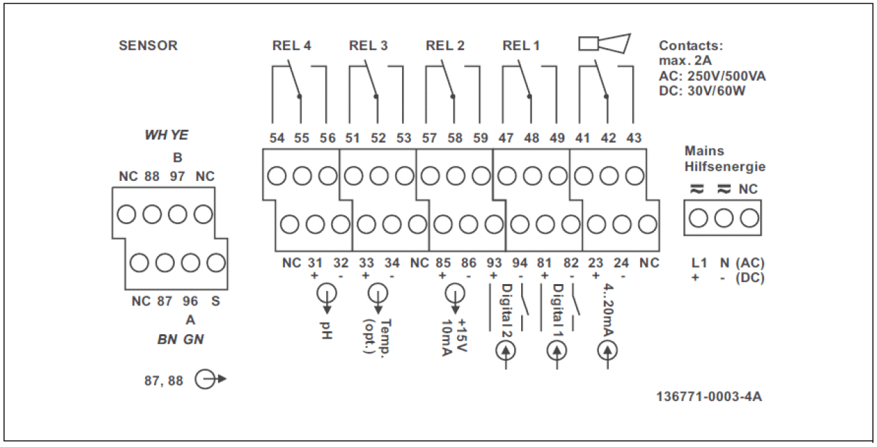
- Affix the corresponding wiring diagram supplied with the unit to the terminal block.
- Connect the brown, white, green, and yellow cable wires to terminals 87, 88, 96, and 97, respectively.
- Do not connect terminals marked “NC” or unmarked terminals.
- Connect 220VAC power to the L1 and N terminals; connect 24VDC power to the + and - terminals.
- Connect the first current output (pH) to terminals 31 and 32, and the second current output (temperature, optional) to terminals 33 and 34. The current output is an active output.
Note: Ensure that all cable glands are tightened and sealed.
2. Key Functions
2.1 Basic Key Function Description
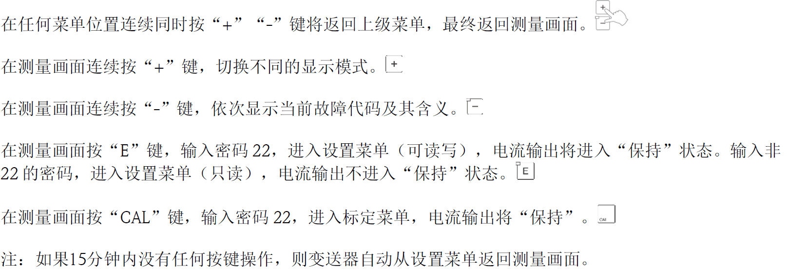
The keys on the transmitter panel are used for parameter setting and calibration. The specific functions are as follows:
- CAL key: Enter calibration mode.
- DIAG key: View diagnostic information.
- OK key: Confirm selection or input.
- Arrow keys: Move the cursor up, down, left, or right, or modify values.
3. Wiring Precautions
- Ensure that the power supply voltage matches the transmitter requirements (220VAC or 24VDC).
- The current output is an active output and does not require an external power supply.
- The shield wire should be properly grounded to reduce interference.
- After all wiring is completed, check whether the terminals are tight to avoid loose connections.
4. Summary
Correct wiring is the foundation for ensuring the normal operation of the CPM253/223 transmitter and pH/ORP sensors. Following the above steps can ensure measurement accuracy and system reliability. If you have any questions, please refer to the supplied wiring diagram or contact technical support.