
CM42 Transmitter Wiring Overview
The CM42 transmitter is a core device in industrial pH/ORP measurement, and its wiring correctness directly affects measurement accuracy and system stability. This article introduces step by step the power/signal wiring and the wiring methods for different types of sensors to help you quickly complete the installation.
Power and Signal Wiring
One Current Output Wiring
The CM42 transmitter supports one current output (optional two). The supply voltage range is 12.5 to 30 VDC. When wiring, terminal 133 connects to the positive voltage, and terminal 134 connects to the negative voltage.
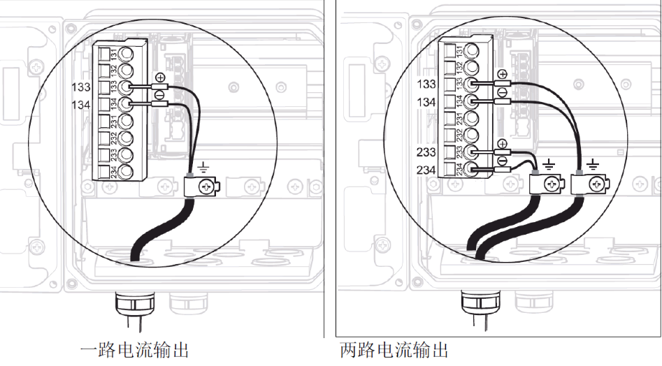
Two Current Output Wiring (Optional)
If the two current output option is selected, the second output corresponds to terminals 233 (positive) and 234 (negative). Please ensure correct power polarity to avoid damaging the transmitter.
Sensor Wiring
Wiring methods differ depending on the sensor type. The following sections describe the wiring steps for standard analog, IsFET analog, and Memosens digital sensors.
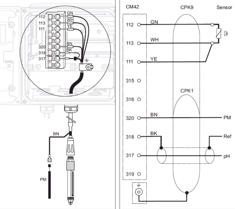
Standard Analog Sensor Wiring (Using CPK9 Cable)
Standard analog sensors usually use a CPK9 cable. The wiring steps are as follows:
- Temperature wire connection: green wire to 112, white wire to 113, yellow wire to 111.
- Signal wire connection: the core wire of the coaxial cable (measurement signal) to 317, the black shielded wire (reference signal) to 318; the brown equipotential wire to 320.
- Shield grounding: the sensor cable shield must be reliably grounded.
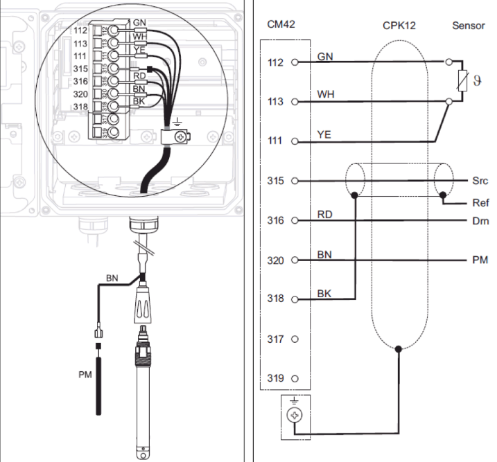
IsFET Analog Sensor Wiring (Using CPK12 Cable)
IsFET sensors require a CPK12 cable. The wiring method is as follows:
- Temperature wire connection: green wire to 112, white wire to 113, yellow wire to 111.
- Signal wire connection: the coaxial core wire (measurement signal) to 315, the black shielded wire (reference signal) to 318, the red wire to 316; the brown equipotential wire to 320.
- Shield grounding: the sensor cable shield must be reliably grounded.
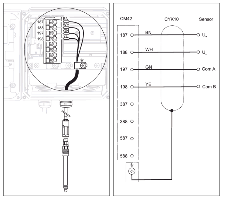
Memosens Digital Sensor Wiring
Memosens digital sensors use a four-wire connection. The wiring steps are as follows:
- Cable wire connection: brown wire to 187, white wire to 188, green wire to 197, yellow wire to 198.
- Shield grounding: the sensor cable shield must be reliably grounded.
Note: All cable glands must be tightened and sealed to ensure the protection rating.
Wiring Precautions
- Be sure to perform wiring operations with the power off to ensure safety.
- Check that the cable specifications match the sensor type to avoid incorrect connections.
- The shield should be grounded at a single point to avoid ground loop interference.
- After wiring is completed, carefully check that all terminals are tightened.
Summary
Correct wiring is the foundation for stable operation of the CM42 transmitter. This article covers the wiring methods for power, signal, and three sensor types. Following the above steps can effectively improve measurement accuracy and extend equipment life. If you have any questions, please refer to the product manual or contact technical support.