
TMT80 Temperature Transmitter Wiring Overview
The TMT80 is a two-wire temperature transmitter that supports thermocouple and RTD inputs. The wiring method directly determines measurement accuracy and operational stability.
This article explains terminal assignments and wiring steps one by one according to the three input types: power supply, thermocouple, and RTD, making it easy for engineering and technical personnel and procurement staff to quickly consult.
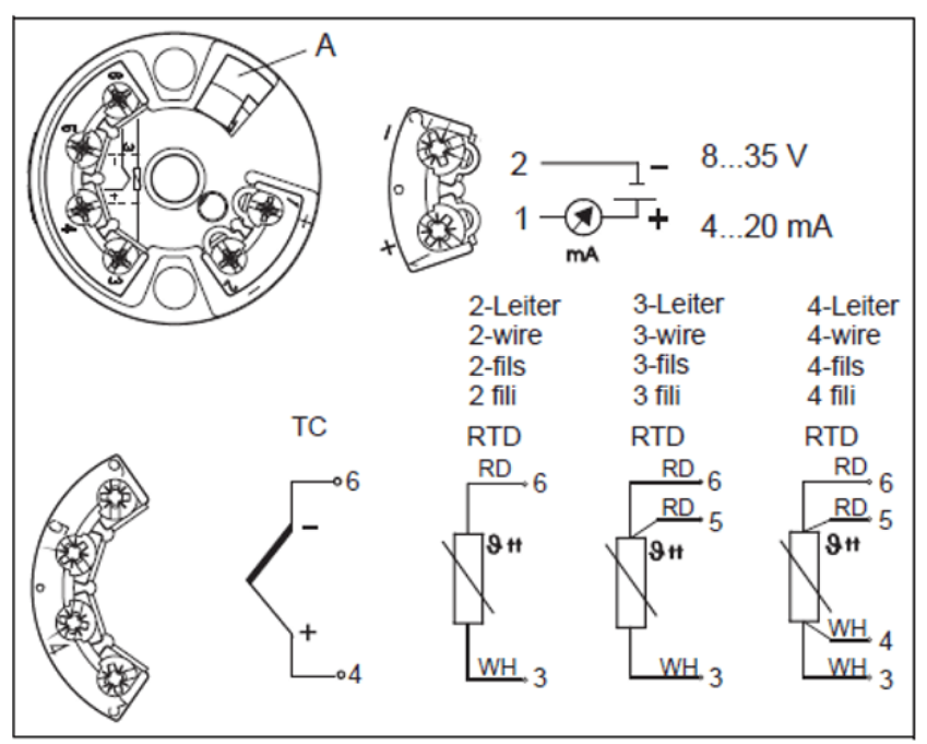
Power Supply Wiring (Two-Wire)
The TMT80 uses a two-wire power supply, with a supply voltage range of 8-35 V DC. Power and signal share the same pair of wires.
- Terminal 1: Power supply positive (1+)
- Terminal 2: Power supply negative (2-)
The supply voltage must remain between 8-35 V DC. Falling below the lower limit may prevent the transmitter from starting normally.
Thermocouple Wiring
When the TMT80 is connected to a thermocouple, the signal input uses terminals 4 and 6.
- Terminal 4: Thermocouple positive (4+)
- Terminal 6: Thermocouple negative (6-)
Note that the thermocouple polarity must not be reversed, otherwise the output signal will drift in the opposite direction.
RTD Wiring
The TMT80 supports two-wire, three-wire, and four-wire RTD connections. The more wires used, the better the lead resistance compensation effect and the higher the measurement accuracy.
Two-Wire RTD
The two-wire connection is the simplest, but it cannot eliminate the effect of lead resistance. It is suitable for applications with low accuracy requirements.
- One end connects to terminal 3
- The other end connects to terminal 6
Three-Wire RTD
The three-wire connection can compensate for single-side lead resistance and is the most commonly used connection in industrial sites.
- One end uses a single wire to terminal 3
- The other end uses two wires to terminals 5 and 6 respectively
Four-Wire RTD
The four-wire connection can completely eliminate lead resistance and is suitable for high-precision measurement scenarios.
- One end uses two wires to terminals 3 and 4
- The other end uses two wires to terminals 5 and 6
Wiring Method Comparison
| Input Type | Terminal Assignment | Accuracy Characteristics |
|---|---|---|
| Thermocouple | 4+, 6- | Suitable for high-temperature measurement |
| Two-Wire RTD | 3, 6 | Simple, lower accuracy |
| Three-Wire RTD | 3; 5, 6 | Commonly used, compensates lead resistance |
| Four-Wire RTD | 3, 4; 5, 6 | High precision, fully compensated |
Wiring Precautions
- Before wiring, confirm that the power supply voltage is within the 8-35 V DC range.
- Thermocouples and RTDs cannot be connected at the same time. Select terminals according to the actual sensor type.
- The leads of three-wire and four-wire RTDs should be equal in length and of the same specification to ensure compensation effectiveness.
- After wiring is completed, check that terminals are tightened to avoid false connections that may cause signal jumps.
Correct wiring is the foundation for stable operation of the TMT80. It is recommended to check one by one against the wiring diagram before powering on for commissioning.