
1. RIA15 Loop Display Measurement Principle
The RIA15 loop display is designed for 4-20 mA or HART® signal loops and can directly display the measured signal or HART® process variables digitally. The display does not require an external power supply and is powered entirely by the loop, which simplifies installation and improves safety.
The device is compatible with HART® 5.0 and above communication protocols and can be used in conjunction. Its LCD screen can display 5-digit scalable measured values and remains clearly readable even under strong lighting conditions.
In addition to displaying measured values, users can easily switch units and bar graph display via three keys. Models with backlit display are optional, but note that the backlight increases the voltage drop.
The RIA15 can be used with specified models of E+H sensors or transmitters, not only displaying measured values but also performing sensor settings. In this case, the "Level" or "Analysis" option must be selected in the ordering options.
2. Power Supply Wiring and Terminal Assignment
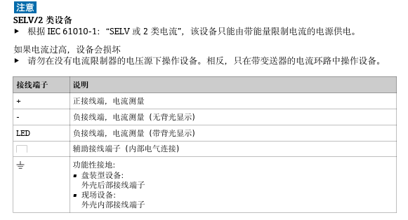
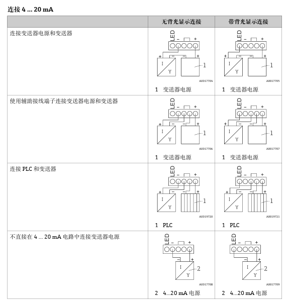
The RIA15 must be connected in series with the instrument in the loop. The specific terminal assignment is shown in the figure below. Please ensure correct wiring to avoid damaging the device or affecting measurement accuracy.
3. Instrument Operating Key Description
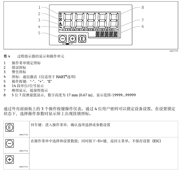
The RIA15 is equipped with three operating keys for menu navigation, parameter setting, and display switching. The key layout is shown in the figure below, and the specific functions are as follows:
- Confirm key: Enter menu or confirm settings
- Up key: Increase value or scroll up
- Down key: Decrease value or scroll down
4. Operating Commissioning Steps
When commissioning the RIA15, please follow the steps below to ensure the display is correctly configured and put into operation.
- Ensure the loop is powered off and connect the RIA15 correctly according to the wiring diagram.
- Turn on the loop power; the display starts and shows the current measured value.
- Use the keys to enter the menu and set the units, range, and display mode as needed.
- If backlight or bar graph display is required, set the corresponding options in the menu.
- After completing the settings, exit the menu and confirm the display is normal.
5. Operating Menu for Use with Micropilot FMR20
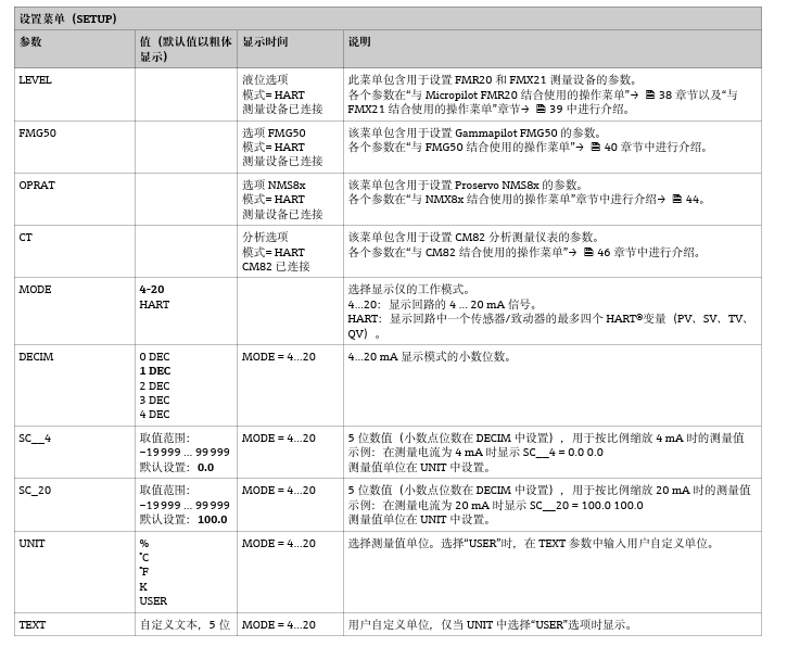
When the RIA15 is used with the Micropilot FMR20 radar level meter, level parameters can be viewed and set directly via the display. The operating menu structure is shown in the figure below, and users can refer to it for quick configuration.
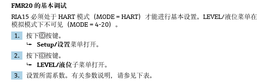
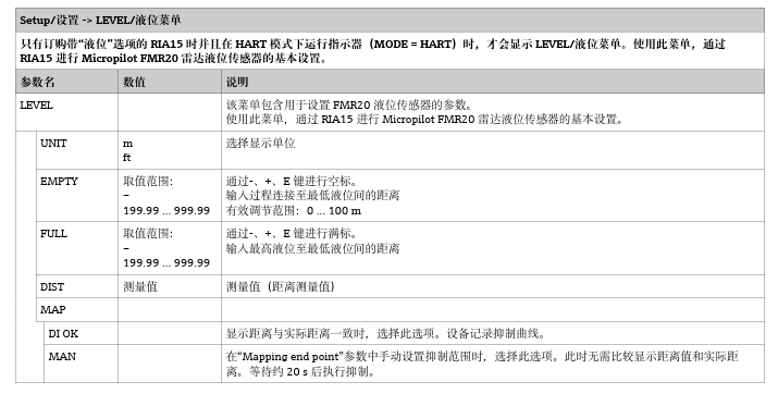
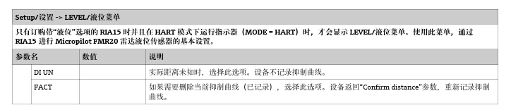
Through the above menus, users can easily complete level measurement settings and monitor measured values in real time. For specific parameter settings, please refer to the relevant device manuals.