
1. Wiring
Correct wiring is the foundation for stable operation of the transmitter. Please follow the steps below to connect the sensor and power supply, and ensure all cable glands are tightened and sealed.
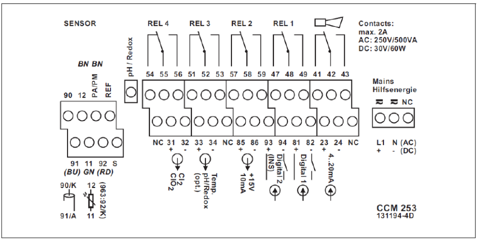
1.1 Connecting CCS140/141/240/241 residual chlorine and chlorine dioxide sensors
- Affix the corresponding wiring diagram provided to the terminal block.
- The residual chlorine or chlorine dioxide sensor has an integrated cable. Connect the green wire to terminal 11, the black wire to terminal 12, the K wire to terminal 90, the red A wire to terminal 91, and the shield to terminal S.
- Connect the pH sensor measurement and reference signals to the "pH" and "REF" terminals respectively; connect the brown equipotential wire to the "PA/PM" terminal.
- Do not connect terminals marked "NC" or unmarked terminals.
- Connect 220VAC power to terminals L1 and N; connect 24VDC power to terminals + and -.
- Connect the first current output (residual chlorine or chlorine dioxide) to terminals 31 and 32, and the second current output (temperature or pH, optional) to terminals 33 and 34. The current output is an active output.
1.2 Connecting CCS120 total chlorine sensor
- Affix the corresponding wiring diagram provided to the terminal block.
- The total chlorine sensor has a TOP68 connector without a cable. Use the CPK9-N*A1B cable together. Connect yellow and white to terminal 11, white to terminal 90, black to terminal 12, green to terminal 85, and brown to terminal 86. Connect the shield to terminal S.
- Do not connect terminals marked "NC" or unmarked terminals.
- Connect 220VAC power to terminals L1 and N; connect 24VDC power to terminals + and -.
- Connect the first current output (total chlorine) to terminals 31 and 32, and the second current output (temperature, optional) to terminals 33 and 34. The current output is an active output.
Note: Ensure all cable glands are tightened and sealed.
2. Key Functions
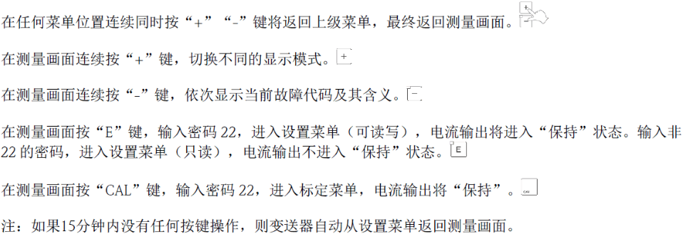
2.1 Basic Key Function Description
3. Settings
Access the menu via keys for parameter settings to ensure the transmitter matches the sensor.
3.1 Sensor Settings
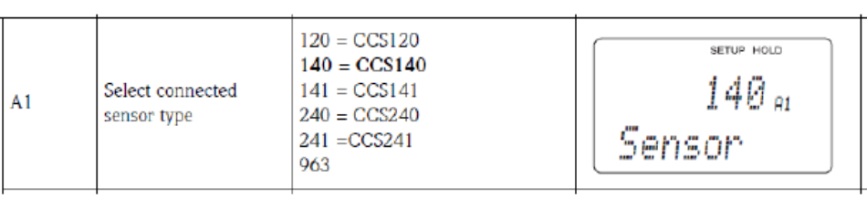
Press the "E" key and enter password "22". In the "SETUP 1" menu, select the corresponding sensor in the "A1" menu.
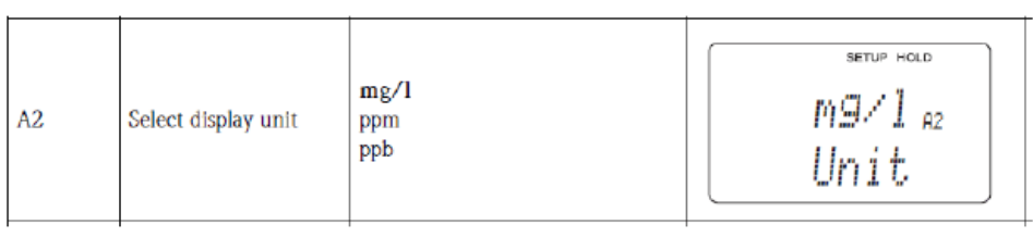
In the "SETUP 1" menu, select the corresponding unit in the "A2" menu.
3.2 pH Compensation Settings
If the system has a pH sensor, select Auto in the "B2" menu under the "SETUP 2" menu.
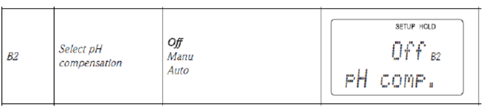
If the system does not have a pH sensor, select Manu in the "B2" menu under the "SETUP 2" menu.
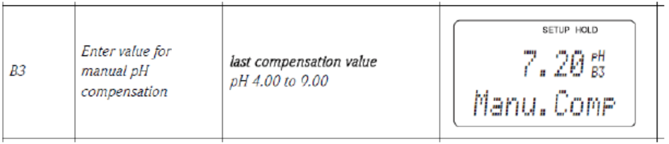
And enter the actual pH value of the water sample in the "B3" menu under the "SETUP 2" menu.
3.3 Range Settings
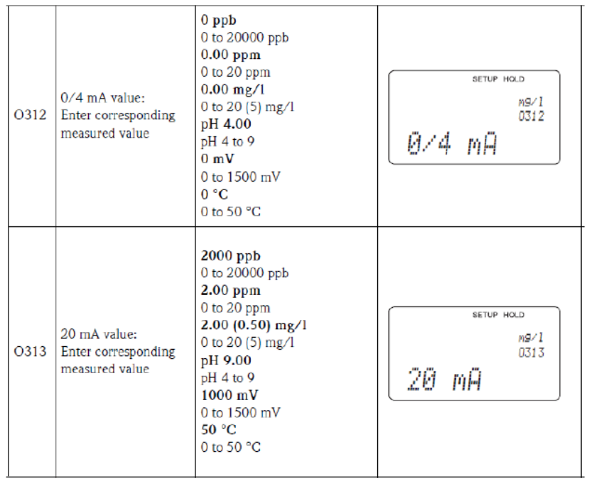
In the "Current Output" menu, set the 4-20mA corresponding range. In 01, select the current output channel. For dual-channel output, there are OUT1 and OUT2 options; for single-channel output, proceed directly to the next item. OUT1 is used as the chlorine current output; OUT2 is used as the temperature or pH current output.
3.4 Instrument Reset
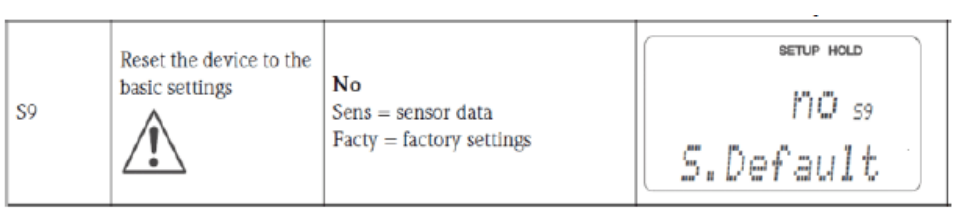
In the "Service" menu, under the "S9" menu, select "Facty" to reset the transmitter.
4. Calibration
Press the "CAL" key and enter password "22". Complete the slope calibration in the "Calibration" menu.
- In the "C11" menu, enter the Cl2 value measured in the laboratory and press the "CAL" key.
- After stabilization, it automatically enters the "C13" menu, displaying the calibrated slope.
- Press the "CAL" key, and the "C14" menu displays whether calibration passed or an error occurred.
- Press the "CAL" key, and in the "C15" menu, choose whether to save the calibration data, discard it, or recalibrate.
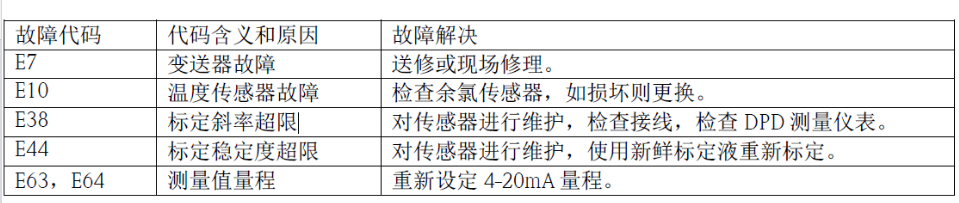
5. Common Fault Codes
6. Sensor Maintenance
Regular maintenance can extend sensor life and ensure measurement accuracy.
- If the membrane is contaminated, clean the sensor.
- Replace the electrolyte quarterly or annually, depending on the specific working conditions.
- Replace the membrane regularly, depending on the specific working conditions.
- Calibrate the sensor when necessary.
6.1 Cleaning the Sensor
- Remove the sensor from the flow-through holder.
- Rinse gently with tap water, or soak in 1-5% hydrochloric acid for a few minutes.
6.2 Replacing the Membrane Head and Electrolyte
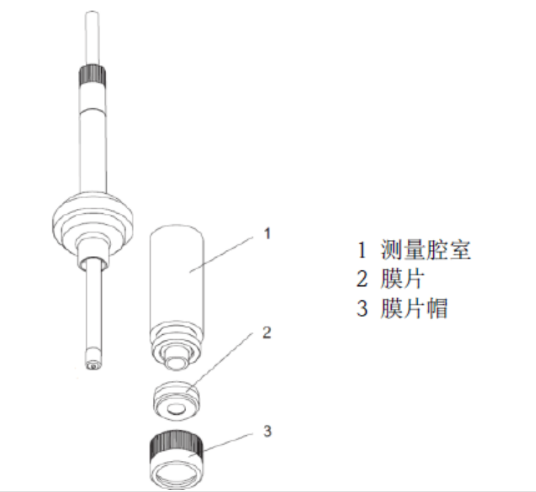
- Unscrew the measuring chamber (position 1).
- Unscrew the membrane cap at the front (position 3) and replace the membrane (position 2).
- Add 7-8ml of electrolyte to the measuring chamber until the liquid level reaches the threads inside the measuring chamber.
- Place the measuring chamber on a flat table and tap it a few times to remove air bubbles from the electrolyte.
- Screw the measuring chamber filled with electrolyte onto the sensor. Excess electrolyte will flow out.
Note:
- The electrolyte has a lifespan of 1 year; yellowed electrolyte must not be used.
- After using the electrolyte bottle, tighten it to prevent the remaining electrolyte from oxidizing.