
CM14 Transmitter Electrical Connection
Correctly completing the electrical connection is the foundation for stable operation of the CM14 transmitter. All operations must follow safety regulations to ensure the safety of equipment and personnel.
Safety Precautions
- All connections must be made under power-off conditions.
- Disconnecting the protective ground can cause danger. Before making other electrical connections, a protective ground connection must first be established.
Transmitter Wiring
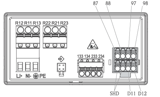
The transmitter wiring is shown in the figure. Please connect the power, signal, and output lines correctly according to the terminal definitions.
Terminal Description
The terminal functions of the CM14 transmitter are shown in the table below. Please refer to it when wiring.
| Terminal No. | Function Description |
|---|---|
| 87 | Brown wire core, sensor power supply U+ connection |
| 88 | White wire core, sensor power supply U- connection |
| 97 | Green wire core, communication signal A |
| 98 | Yellow wire core, communication signal B |
| SHD | Shield layer |
| D11 | Connect alarm output (+) |
| D12 | Connect alarm output (-) |
| L+ | Transmitter power supply positive pole |
| L- | Transmitter power supply negative pole |
| 133 | Connect analog output 1 (+) |
| 134 | Connect analog output 1 (-) |
| 233 | Connect analog output 2 (+) |
| 234 | Connect analog output 2 (-) |
| R11, R12, R13 | Connect relay 1 |
| R21, R22, R23 | Connect relay 2 |
Post-Connection Check
- Check whether the supply voltage matches the technical parameters on the nameplate.
- Confirm that the power cable and signal cable are connected correctly.
Display Interface and Operation
The CM14 transmitter is equipped with an intuitive display interface and buttons for on-site operation and monitoring.
Display Area Description
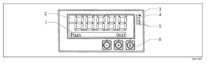
- 1 Dot matrix display area
- 2 7-segment display area
- 3 LED status indicator, indicating power is on
- 4 LED status indicator, indicating alarm function
- 5 LED status indicator, indicating the limit contact status of relay 1/2
On-Site Operation Buttons
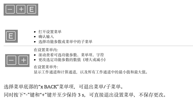
On-site operation is performed via the three built-in buttons on the front panel of the device.
Power-On Display and Menu Setup
After power-on, the transmitter by default allows the user to access the Setup, Diagnostics, and Calibration menus (factory settings). The device settings can also be locked.
Menu Operation Steps
- After power-on, press the E key to enter the setup menu.
- Press the + key repeatedly until the Setup menu is displayed.
- Press the E key to open the Setup menu.
Setup Menu Parameter Description
| Parameter | Description |
|---|---|
| Current range | Selectable output current (0-20) mA or (4-20) mA |
| Out 1 0/4 mA | Set the actual value corresponding to the lower limit of the analog output range. If the set value is lower than the lower range limit, the current output is set to the saturation current 0/3.8 mA. |
| Out 1 20 mA | Set the actual value corresponding to the upper limit of the analog output range. If the set upper range limit is exceeded, the current output is set to the saturation current 20.5 mA. |
| Out 2 0/4 mA | Set the lower range limit corresponding to the temperature input. If the set value is lower than the lower range limit, the current output is set to the saturation current 0/3.8 mA. |
| Out 2 20 mA | Set the upper range limit corresponding to the temperature input. If the set upper range limit is exceeded, the current output is set to the saturation current 20.5 mA. |