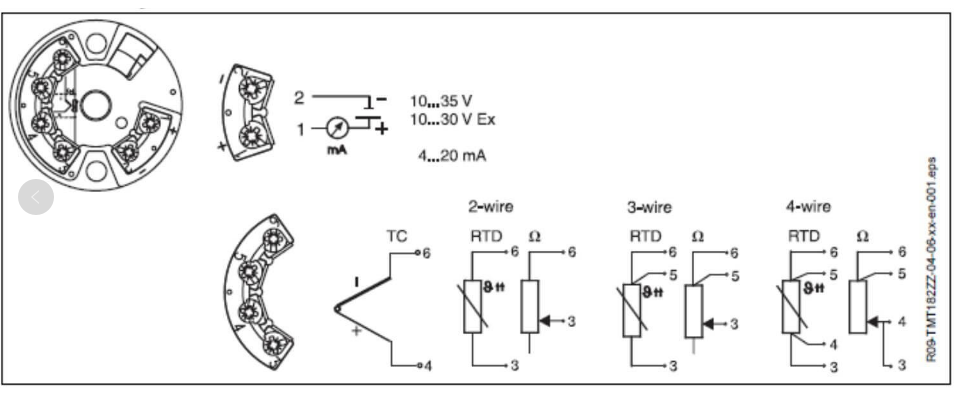
Overview of Three Common Wiring Systems for RTDs
The lead wire method of an RTD directly affects measurement accuracy and on-site adaptability. In industrial sites, three wiring methods are common: two-wire, three-wire, and four-wire. The core difference lies in whether they can eliminate the additional error caused by lead resistance. When selecting, one must comprehensively judge based on measurement accuracy, wire length, cost, and installation conditions.
Two-Wire Lead Method
Connecting one lead to each end of the RTD element is called two-wire. This method is simple in wiring and low in cost, so many RTD products adopt this form.
Main Problems of Two-Wire
- It introduces additional error from lead resistance, and the measurement error is related to the wire material and length.
- The lead and connecting wires should not be too long; otherwise, the error increases significantly.
- When the lead wire length of the RTD element is greater than 500mm, it is recommended to switch to three-wire to eliminate the effect of lead resistance.
Applicable Scenarios for Two-Wire
Two-wire is only suitable for occasions with low measurement accuracy requirements. If the on-site temperature accuracy requirement is not high and the wires are short, two-wire can be prioritized to reduce costs.
Three-Wire Lead Method
Connecting two leads to one end of the RTD sensing element and one lead to the other end is called three-wire. It can eliminate the influence of internal leads, and its measurement accuracy is higher than that of two-wire.
Working Principle of Three-Wire
Three-wire is often used in conjunction with a bridge circuit. Two wires are connected to two arms of the bridge respectively, and the other wire is connected to the bridge power supply, thereby eliminating the influence of lead resistance changes.
Applicable Scenarios for Three-Wire
- Occasions where the temperature measurement range is narrow, the wires are too long, or the temperature easily changes during wiring.
- Industrial sites where measurement errors caused by lead resistance changes need to be reduced or eliminated.
Four-Wire Lead Method
Connecting two leads to each end of the RTD element is called four-wire. Two of the leads provide a constant current to the RTD, converting resistance into a voltage signal, and the other two leads transmit the voltage signal to the measuring instrument.
Accuracy and Cost of Four-Wire
- It can completely eliminate the effect of lead resistance, providing the highest measurement accuracy.
- The structure is complex and the cost is relatively high, so it is mostly used in laboratories and high-precision industrial measurements.
Comparison of the Three Wiring Systems and Selection Recommendations
| Wiring System | Number of Leads | Effect of Lead Resistance | Measurement Accuracy | Typical Applications |
|---|---|---|---|---|
| Two-wire | 2 | Cannot be eliminated | Relatively low | Short-distance, low-cost occasions |
| Three-wire | 3 | Can be reduced or eliminated | Relatively high | Long-distance, temperature-fluctuating occasions |
| Four-wire | 4 | Completely eliminated | Highest | Laboratories, high-precision industrial measurements |
Wiring of RTDs on E+H Temperature Transmitters
In actual engineering, when connecting an RTD to an E+H temperature transmitter, it is necessary to wire correctly according to the wiring system supported by the transmitter. The figure below shows a typical wiring method for on-site installation reference.