
1. Check the Nameplate
Before wiring, be sure to check the transmitter nameplate to confirm that the device specifications match the on-site requirements. The nameplate contains the following key information:
- Order number/serial number: Used to identify the device model and version.
- Power supply/frequency, power consumption: Note whether the power supply is 220VAC or 24VDC.
- Input/output: I-OUT (HART) is current output (HART); f-OUT is frequency output.
- Reserved additional information for the device version: approvals, certificates, etc.
- Protection class: such as IP67, etc.
- Permissible ambient temperature range: Ensure that the operating ambient temperature is within the permissible range.
- Please observe the operating procedures: Strictly follow the manual.

2. Terminal Compartment Nameplate Wiring Diagram
The terminal compartment nameplate provides terminal assignment and electrical parameters, and is an important basis for wiring. Please refer to the figure below:
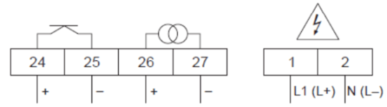
The terminal definitions are as follows:
- Terminal numbers 1/2: L1(L+)/N(L-), power supply.
- Terminal numbers 26/27: I-OUT (HART) Active, 4...20mA, RLmax = 700 ohms, HART RLmin = 250 ohms.
- Terminal numbers 24/25: PULSE-OUT, fmax = 100Hz, Passive: 30VDC, 250mA.
3. Electrical Connection of Power Supply and Measurement Unit
The electrical connection diagram of the transmitter (field-mounted aluminum housing) is shown below. The maximum cross-sectional area of the connecting cable is 2.5 mm² (AWG 13).
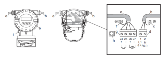
Explanation of the labels in the figure:
- a: Terminal compartment cover
- b: Power supply cable: 85...260VAC / 20...55VAC / 16...62VDC
- c: Power supply connection terminals
- d: Power supply cable terminals: terminals 1-2
- e: Signal cable
- f: Signal cable grounding terminal
- g: Signal cable terminals: terminals 24-27
- h: Service interface
- i: Potential equalization grounding terminal
4. Terminal Assignment of Prosonic Flow 91W
Please refer to the figure below for the terminal assignment of Prosonic Flow 91W:

5. Sensor/Transmitter Connecting Cable
Note! The sensor is connected with two single-core cables, and the shielding layer is grounded through the grounding ring at the cable gland opening (A). The grounding connection is a prerequisite for correct measurement.
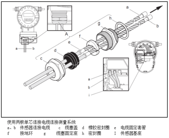
The connection steps are as follows:
- Loosen the cable gland cover (c). Remove the rubber sealing ring (d).
- Pass the sensor connecting cables (a, b) through the cable gland cover.
- Pass the sensor connecting cables respectively through the grounding ring on the cable gland fixing seat (g) and into the terminal compartment.
- Insert the connectors of the sensor connecting cables. The left side is the upstream sensor (a), and the right side is the downstream sensor (b). Connect the connectors correctly until they engage with a "click".
- Place the rubber sealing ring (d) along the side cutout (for example, using a screwdriver) to secure the cable correctly in place. Push the rubber sealing ring into the cable gland until the sensor cable sleeve presses tightly against the grounding ring.
- Seal the cable gland cover (c).
- In the terminal compartment, secure the two sensor connecting cables to the sensor base (the sensor base is a standard supplied item).
Prosonic Flow W DN 15 - 65 (/2 - 2/2') Grounding via Cable Gland
The connection and grounding diagram of the measuring system is shown below:
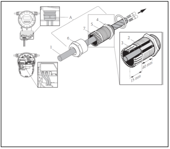
Labels in the figure:
- 1: Cable sheath
- 2: Exposed braided shielding layer (prepared)
- 3: Rubber sleeve
- 4: Internal grounding contact point on this surface (not externally inspectable)
- 5: Cable gland
- 6: Cable gland cap
- 7: Grounding mechanism
Operating steps:
- Screw the cable gland (5) into the transmitter housing.
- Pass the sensor connecting cable through the cable gland cap (6).
- Push the sensor connecting cable into the transmitter housing. Align the outer end of the rubber sleeve (3) with the end of the cable gland (5)/grounding mechanism (7). This ensures that the cable gland: a) seals; b) properly grounds the cable to the internal contact point (4) of the transmitter housing after the cable is fastened.
- Tighten the cable gland cap (6) clockwise. Since external inspection is not possible, it is essential to follow this instruction.
Note: A cable marked in red indicates the sensor is "upstream"; a cable marked in blue indicates the sensor is "downstream".
Note: The cable gland can be removed from the cable by loosening and removing the cable gland cap. Then use tweezers to retract the grounding mechanism (7). No excessive force is required when retracting (excessive force will damage the shielding layer). It may be necessary to turn the cable gland clockwise to push the grounding mechanism further forward, thereby removing the internal hook of the grounding mechanism from the locked position. Remove the cable gland cap again. Then try to retract it again.