
Prosonic 91 Ultrasonic Level Meter Probe Installation and Quick Setup
Prosonic 91 is a commonly used ultrasonic level measurement instrument in industrial sites. The quality of its probe installation directly determines measurement accuracy and long-term stability. This article is aimed at engineering technicians and procurement personnel, outlining the key steps for probe installation and quick setup. The following content, combined with on-site diagrams, can help you complete commissioning in a short time.
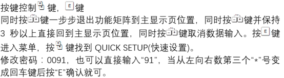
1. Pre-installation Preparation
1.1 Installation Location Selection
- The probe should be installed perpendicular to the surface of the measured medium to avoid echo deviation caused by tilting.
- Keep away from areas prone to interference echoes such as feed inlets and agitators.
- Ensure a blind zone distance is maintained between the probe and the highest level to prevent measurement failure.
- Avoid installing directly above protruding structures such as tank welds and brackets.
1.2 Environment and Working Condition Confirmation
- Confirm that the process temperature and pressure are within the allowable range of the instrument.
- Check whether the medium generates large amounts of foam, steam, or dust. If necessary, select a corresponding protective probe type.
- Verify the supply voltage and output signal type to ensure compatibility with the control system.
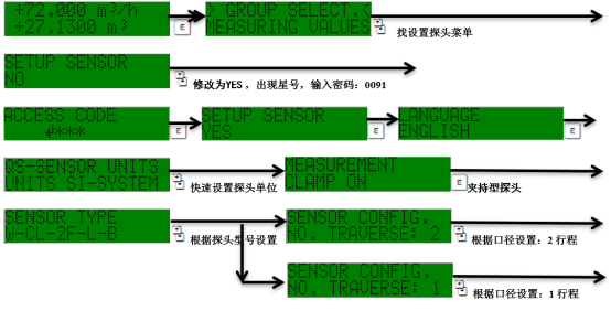
2. Probe Installation Steps
- Open a hole at the selected location and install the flange or threaded connection, ensuring good sealing.
- Slowly screw or insert the probe into the mounting seat to avoid damaging the transducer surface.
- Adjust the probe angle so that its axis is perpendicular to the medium surface, and tighten the fixing nut.
- Check the distance between the probe and the tank wall or obstacles to meet the minimum installation spacing requirements.
- After completing the mechanical installation, perform electrical wiring and confirm that the shielding layer is reliably grounded.
3. Quick Setup and Parameter Configuration
3.1 Basic Parameter Settings
| Parameter Item | Description | Typical Setting |
|---|---|---|
| Empty Tank Height | Distance from probe to tank bottom | Input according to actual measurement |
| Full Scale | Maximum measurement range | Set according to process requirements |
| Blind Zone | Near-end area that cannot be measured | Refer to instrument manual |
| Output Signal | 4-20mA/HART, etc. | Match with system |
3.2 Commissioning Key Points
- Use empty tank calibration and full tank calibration to calibrate the measurement reference.
- Observe the echo curve and eliminate false echo interference.
- Set an appropriate damping time to suppress reading fluctuations caused by liquid level fluctuations.
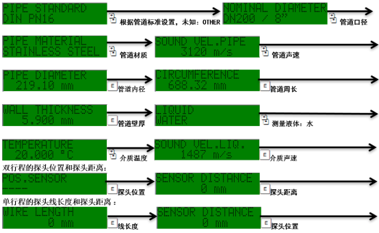
4. Common Problems and Troubleshooting
- Measurement value jumping: Check whether the probe is affected by agitation or feed interference, and adjust damping or installation position.
- No echo signal: Confirm that the probe surface is clean, wiring is correct, and the range setting is reasonable.
- Accuracy deviation: Re-execute empty tank and full tank calibration, and verify the medium sound velocity parameters.
5. Summary
Correct probe installation and standardized quick setup are the foundation for stable operation of the Prosonic 91. It is recommended to record key parameters after installation for later maintenance and fault comparison. For more detailed wiring diagrams and parameter tables, please refer to the product manual or contact the manufacturer's technical support.