
Prosonic 92F Installation Guide
Correct installation of the Prosonic 92F ultrasonic flowmeter is crucial for measurement accuracy and long-term stability. Based on official installation specifications, this article systematically outlines key aspects including installation location, orientation, heat tracing, insulation, straight pipe length, and transmitter installation, for the reference of engineering technicians and procurement personnel.
1. Installation Location
The installation location should avoid gas accumulation or bubbles in the pipe, which would increase measurement error or even interrupt measurement. Please avoid the following locations:
- Highest point of the pipe: prone to gas accumulation.
- Directly above a downward-draining pipe: likely to cause an empty pipe.
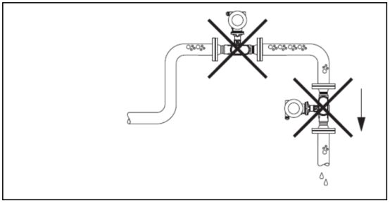
When installing on a downward-draining pipe, it is recommended to install an orifice plate or a section of reduced-diameter pipe as shown in the figure below to prevent the pipe from running empty. A typical application is batch control.
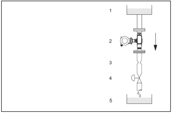
In the figure: 1=supply tank; 2=sensor; 3=orifice plate (pipe fitting); 4=valve; 5=metering tank.
2. Installation Orientation
Always ensure that the arrow on the sensor nameplate points in the same direction as the fluid flow in the pipe.
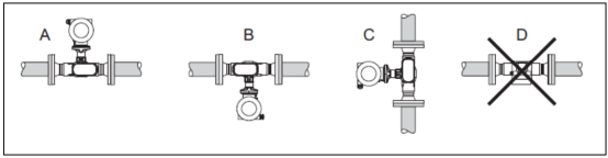
Installation orientation diagram: A, B and C are recommended installation orientations; D is the installation orientation under specific application conditions.
3. Heat Tracing
When measuring certain fluids, heat exchange effects at the sensor must be avoided. It is recommended to equip the instrument with electrical heat tracing (e.g., electric heating elements) or use a heat jacket.
Caution!
- Avoid overheating the electronic components! Ensure that no insulation material is used at the connection between the sensor and the transmitter, or between the terminal compartment cover of a remote version instrument. Strictly following the installation guide for instrument installation can effectively reduce the temperature at the electronic components.
- For instruments using electrical heat tracing, if the heat tracing operates on a phase-angle control or pulse control principle, electromagnetic interference is unavoidable. For example, the electromagnetic interference value exceeds that specified in EN standards (sinusoidal signal: 30A/m). In this case, magnetic field shielding measures must be taken for the sensor.
4. Insulation
When measuring certain fluids, heat exchange at the sensor must be avoided. Various insulation materials are available to meet insulation requirements.
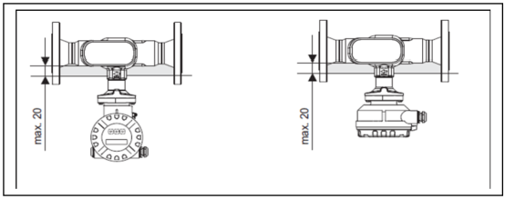
Please note: the maximum insulation thickness at the electronic components/extension neck is 20mm. When the instrument is installed horizontally (transmitter head facing up), the minimum insulation thickness is 10mm to avoid heat exchange. However, be sure not to exceed the maximum insulation thickness of 20mm.
5. Upstream and Downstream Straight Pipe Lengths
If possible, the sensor installation location should preferably avoid valves, tees, elbows and other pipe fittings. It is recommended to observe the following upstream and downstream straight pipe length requirements to ensure measurement accuracy. When two or more pipe fittings are present, the maximum upstream straight pipe length requirement must be met.
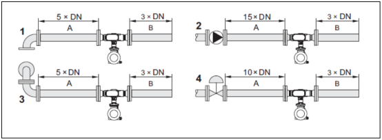
Schematic diagram of minimum upstream and downstream straight pipe lengths for different pipe configurations: A=upstream straight pipe length; B=downstream straight pipe length; 1=90° elbow or tee; 2=pump; 3=2x90° elbow (in different planes); 4=control valve.
6. Transmitter Installation
1. Rotating the Transmitter Housing
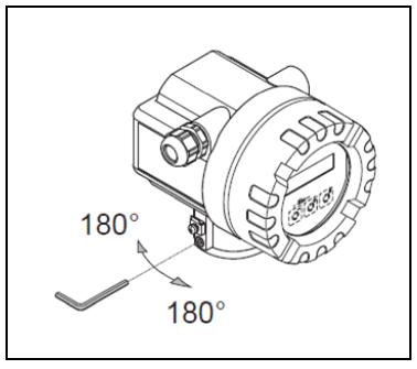
- Loosen the fixing screw.
- Rotate the transmitter housing to the desired position (max. 180°). There is a stop at every 90° on the rotation axis (only for compact versions), making it easier to align the transmitter.
- Tighten the fixing screw.
2. Turning the On-site Display
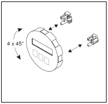
- Loosen the screws on the electronics terminal compartment cover and remove it from the transmitter housing.
- Remove the display module from the transmitter slot.
- Turn the display to the desired position (maximum rotation angle of 4x45° in each direction) and reattach it in the slot.
- Reinstall the electronics terminal compartment cover on the transmitter housing.
3. Installing the Remote Version Instrument
The transmitter can be mounted directly on a wall or on a pipe.
3.1 Direct Wall Mounting
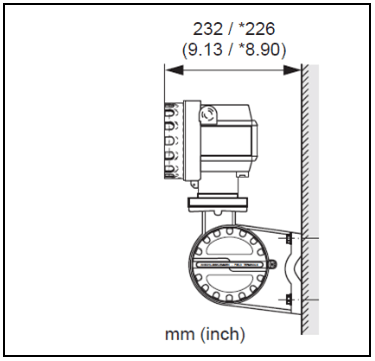
Caution!
- The temperature at the installation location must not exceed the ambient temperature range.
- Avoid direct sunlight.
★ Dimensions of the instrument without a local display unit
3.2 Column Mounting
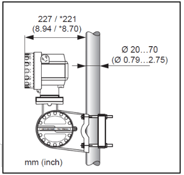
Caution!
- The temperature at the installation location must not exceed the ambient temperature range.
- Avoid direct sunlight.
- If the device is installed on a hot pipe, ensure that the housing temperature does not exceed the maximum permissible temperature value.
★ Dimensions of the instrument without a local display unit