
Overview of the E+H TID10 Temperature Transmitter Display
TID10 is a display unit designed for temperature transmitters by Endress+Hauser (E+H), mainly used for local display and commissioning of on-site temperature signals. It can be used with various E+H temperature transmitter modules to achieve intuitive reading of measured values and rapid parameter setting.
For engineering technicians and procurement personnel, understanding the positioning and functional boundaries of the TID10 helps accurately match transmitter models during the selection stage and avoids rework caused by incompatible display units.
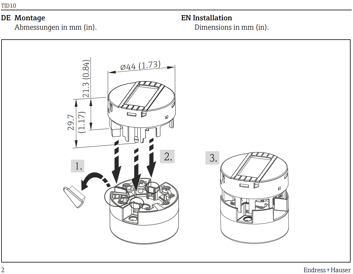
Core Functions of the TID10 Display
Local Display and Reading
- Real-time display of temperature measurement values, with support for switching engineering units;
- Can display current output values for loop verification;
- Equipped with a backlight function, suitable for dim working conditions.
Commissioning and Parameter Setting
- Basic parameter configuration such as range and units can be completed via the display buttons;
- Supports communication with the transmitter module to read internal diagnostic information;
- Can display fault codes to assist in quickly locating problems on site.
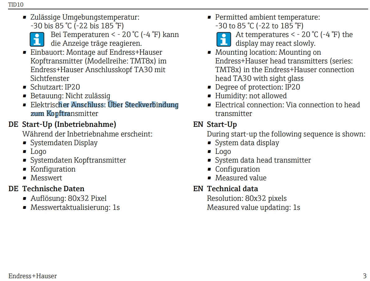
Comparison of Main Parameters and Specifications of the TID10
The table below summarizes the key specifications of the TID10 display for easy matching and verification with the transmitter body during selection.
| Item | Specification Description |
|---|---|
| Compatible Equipment | E+H temperature transmitter modules (specific models subject to the datasheet) |
| Display Method | Digital liquid crystal display, with backlight support |
| Operation Method | Panel button operation |
| Installation Form | Integrated installation with the transmitter or remote display |
| Protection Rating | Determined by the overall assembly form |
Key Points for Installation and Wiring
Installation Steps
- Confirm that the transmitter module is powered off to avoid damage to the interface from hot plugging;
- Align the TID10 display with the transmitter display interface and insert it evenly and firmly into place;
- Check whether the buckle or fixing structure is locked to prevent loosening due to on-site vibration;
- After power-on, observe whether the display lights up normally and enters the measurement interface.
Wiring and Loop Inspection
- Confirm that the supply voltage is within the allowable range of the transmitter;
- Check the polarity of the 4-20mA loop to avoid no display caused by reverse connection;
- Use a multimeter to measure the loop current and cross-verify it with the displayed value.
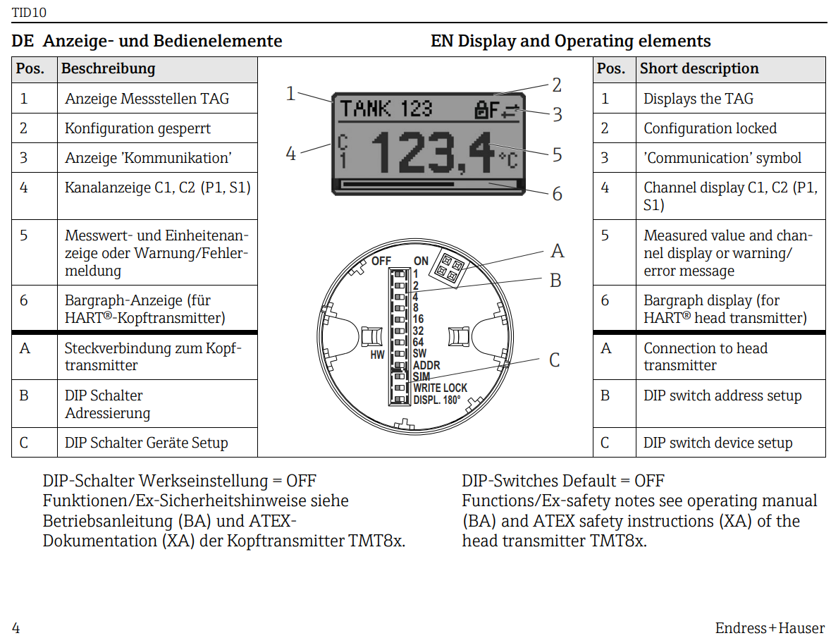
Parameter Setting and Operation Process
Parameter setting should be carried out after understanding the process range. Incorrect range configuration will directly affect the consistency between the 4-20mA output and the host computer display.
- Enter setting mode: press the specified key combination to enter the parameter menu;
- Select parameter item: switch to the target parameter such as range, unit, or damping;
- Modify the value: adjust to the process-required value via the buttons;
- Save and exit: after confirming the save, return to the measurement interface and verify the displayed value.
Common Faults and Troubleshooting Suggestions
- No display: Check the power supply and loop wiring, and confirm that the display is properly inserted;
- Displayed value does not match actual value: Verify the range setting and sensor type;
- Display flickering or abnormal codes: Consult the fault code table in the manual to determine whether it is a sensor open circuit or short circuit;
- Buttons unresponsive: Confirm whether it is in locked state or the buttons are damaged.
Selection and Procurement Suggestions
When purchasing the TID10, the transmitter body model, display interface type, and on-site protection requirements should also be confirmed to avoid incompatibility caused by purchasing the display unit separately.
It is recommended to obtain the latest version of the manual and selection datasheet through official E+H channels or authorized distributors first to ensure that parameters and certification information are accurate and valid.