Promag 10 5XBB Installation and Wiring Overview
Promag 10 5XBB is an electromagnetic flowmeter launched by Endress+Hauser, widely used in industrial process measurement. Correct installation and wiring are the foundation for ensuring measurement accuracy and long-term stable operation.
Based on official technical materials, this article systematically outlines installation and wiring key points for reference by engineering technicians and procurement personnel.
Installation Guide
Installation Location Selection
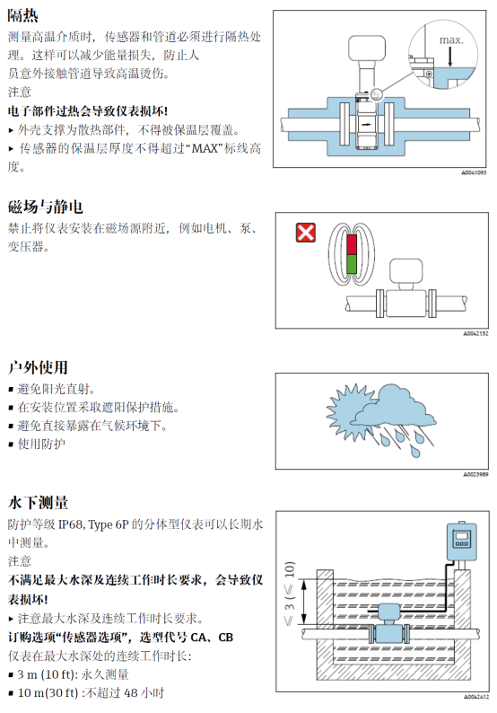
The installation location should avoid strong electromagnetic interference, severe vibration, and high-temperature environments. Ensure the sensor is always filled with liquid to prevent empty pipe.
It is recommended to install at the low end of the pipeline or on an ascending pipe section to ensure full pipe. If the pipeline is a descending pipe, sufficient back pressure must be provided or the pipe diameter reduced.
Pipeline Requirements
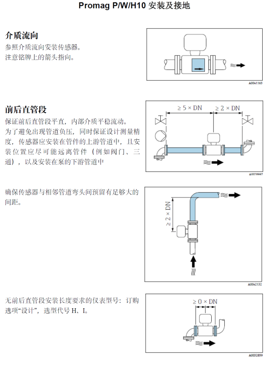
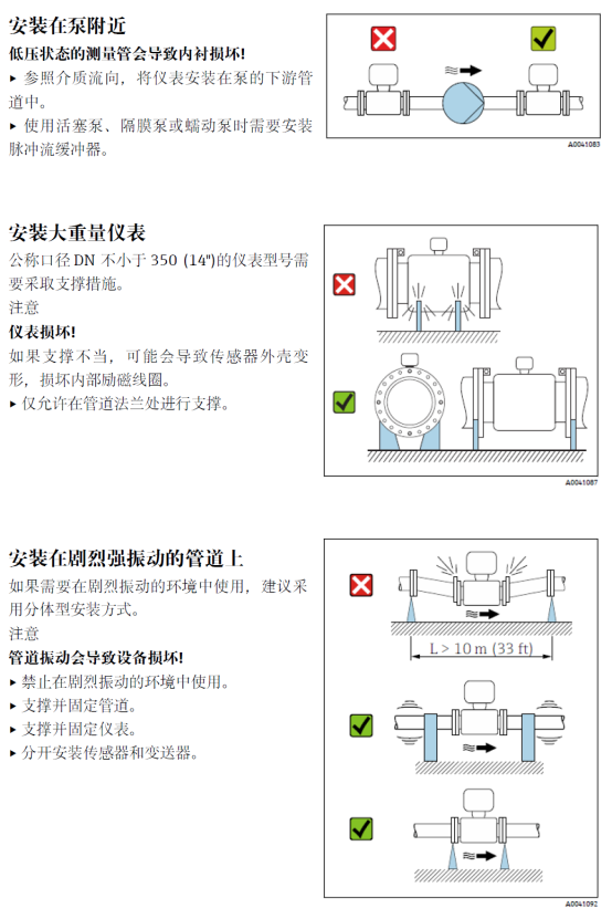
Sufficient straight pipe sections must be reserved before and after the sensor: at least 5DN for the upstream straight pipe and at least 3DN for the downstream straight pipe. If there are disturbances such as elbows or valves, the straight pipe sections should be appropriately extended.
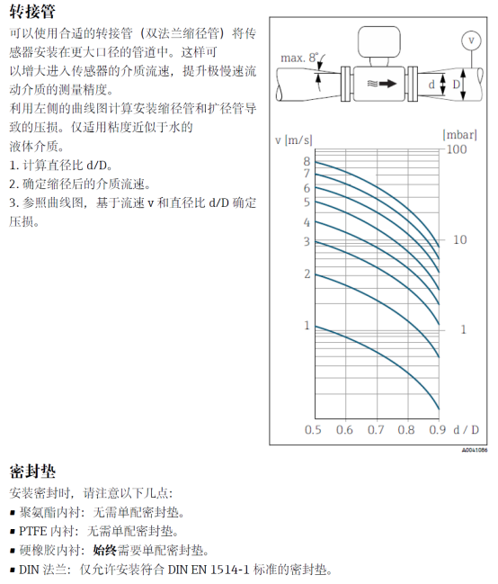
The inner diameter of the pipeline should match the nominal diameter of the sensor to avoid measurement errors caused by diameter reduction or expansion.
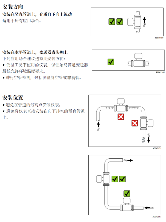
Installation Steps
- Confirm that the pipeline has been depressurized, drained, and cooled to a safe temperature.
- Install the sensor onto the pipeline according to the flow direction arrow, ensuring the arrow direction matches the fluid direction.
- Evenly tighten the flange bolts to avoid liner deformation caused by over-tightening on one side.
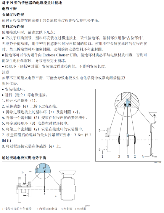
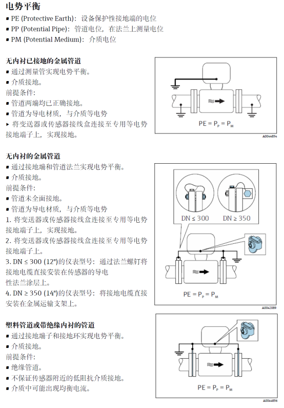
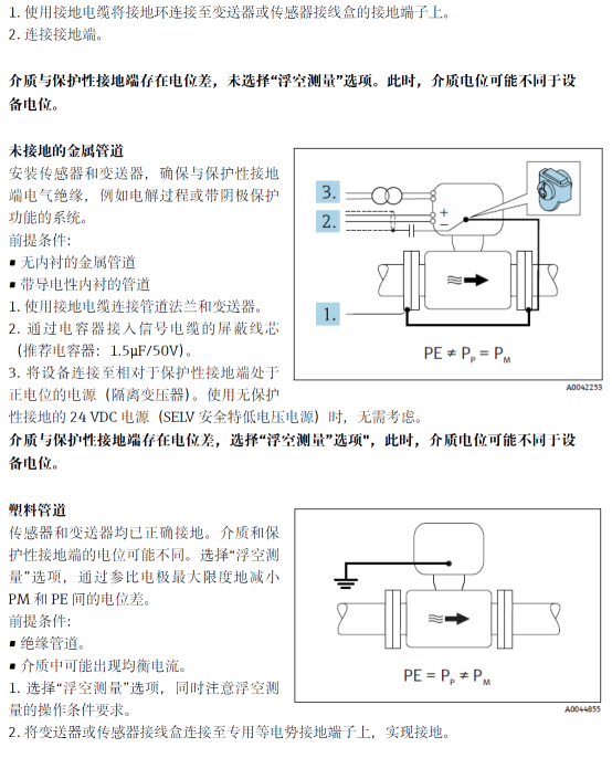
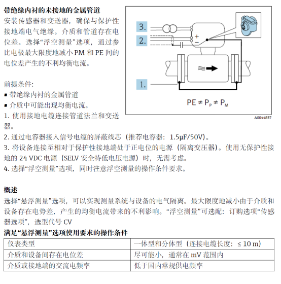
- Check the sensor grounding to ensure reliable connection of the grounding ring or grounding electrode.
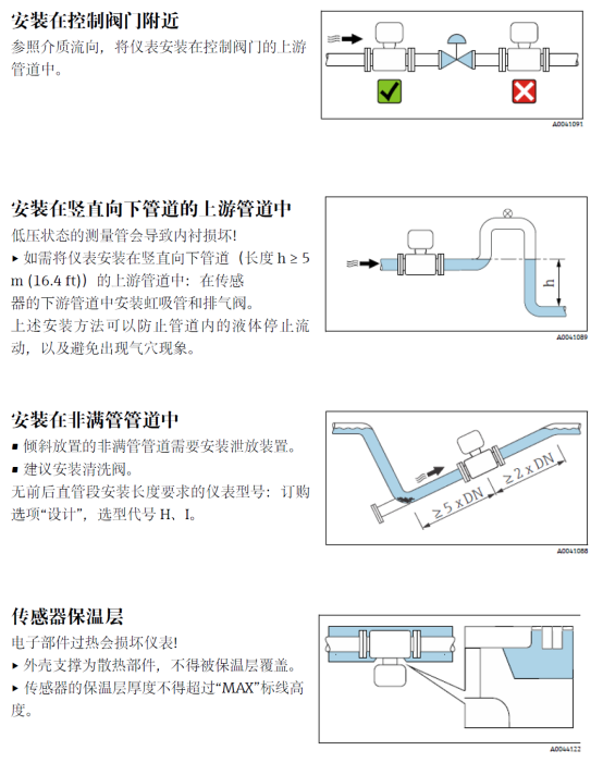
Installation Precautions
- Avoid installation on the suction side of the pump to prevent negative pressure from damaging the liner.
- For media prone to scaling, regular cleaning is recommended, and a detachable sensor should be selected.
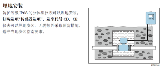
- In explosive atmospheres, explosion-proof regulations must be followed, and corresponding certified cables and sealing joints must be used.
Wiring Guide
Preparation Before Wiring
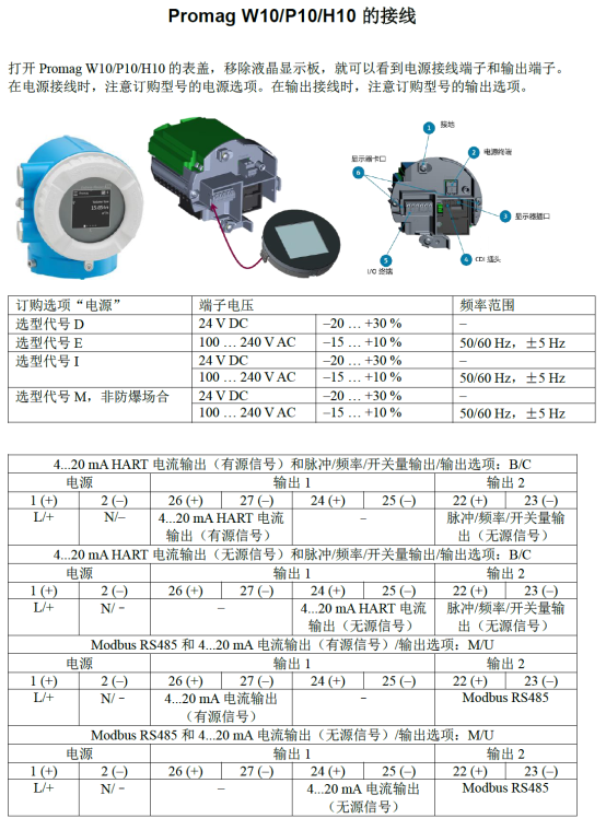
Confirm that the power supply matches the transmitter nameplate, typically 24V DC or 100-230V AC. Prepare suitable cables; shielded cables are recommended.
Disconnect the power supply to ensure no power during wiring. Check that the cable sealing joints are intact.
Terminal Definitions
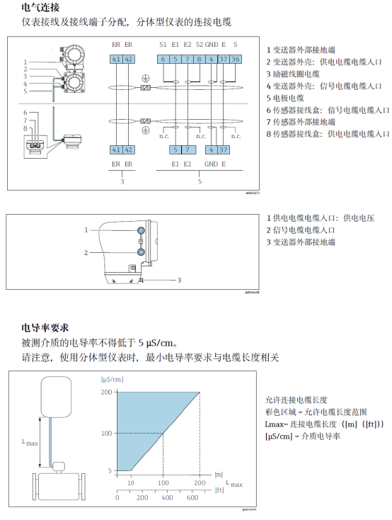
Transmitter terminals include power supply, current output, pulse/frequency output, status input, etc. For specific definitions, please refer to the wiring diagram.
| Terminal | Function | Description |
|---|---|---|
| L/+ | Power Positive | 24V DC or AC Live |
| N/- | Power Negative | 24V DC or AC Neutral |
| +/- | Current Output | 4-20mA, active or passive |
| P/F | Pulse/Frequency Output | Open collector, external power required |
Wiring Steps
- Loosen the transmitter housing cover to expose the wiring terminals.
- Pass the cable through the sealing joint, strip the insulation, and expose an appropriate length of conductor.
- Connect the power and signal lines according to the terminal definitions, ensuring secure connections.
- The shield layer should be grounded at one end, usually at the transmitter side grounding terminal.
- Tighten the sealing joint to ensure the protection rating.
- Replace the housing cover and connect the power supply.
Wiring Precautions
- Power and signal lines should be routed separately, avoiding parallel routing to reduce interference.
- In areas with frequent lightning, installing surge protectors is recommended.
- After wiring, check insulation resistance to ensure no short circuit or ground fault.
Commissioning and Inspection
After power-on, the transmitter performs a self-test, and the display should light up normally. Check parameter settings, such as pipe diameter and medium conductivity.
Perform zero calibration: ensure the pipeline is filled with static liquid, then execute zero adjustment. Then introduce fluid and check whether the output signal is normal.
Common Problems and Solutions
| Problem | Possible Cause | Solution |
|---|---|---|
| No display | Power not connected | Check power cable and terminal connections |
| Abnormal output signal | Wiring error or interference | Check signal line shielding and grounding |
| Fluctuating measurement | Pipe not full or bubbles | Ensure full pipe and remove bubbles |
Summary
The installation and wiring of the Promag 10 5XBB must strictly follow specifications to ensure measurement accuracy and equipment lifespan. This article covers key steps and precautions for reference by technical personnel.
After correct installation and wiring, necessary commissioning and inspection can effectively reduce faults and improve system reliability.