
E+H Vortex Flowmeter Prowirl F200 Installation Guide
Correct installation is key to ensuring the measurement accuracy of the E+H vortex flowmeter Prowirl F200. Based on official technical materials, this article summarizes the installation position, orientation selection, and precautions for high-temperature media, for reference by engineering and technical personnel and procurement staff.
1. Installation Position
Before installation, please check the arrow direction on the sensor nameplate to ensure that the arrow is consistent with the flow direction of the medium in the pipeline. A stable flow state is the prerequisite for accurate volumetric flow measurement by a vortex flowmeter. The figure below shows the relative relationship between the fluid flow direction and the bluff body.
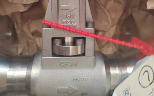
Fluid direction on the sensor body and the direction of the bluff body
1.1 General Principles of Installation Orientation
The flowmeter can be installed in any orientation in the pipeline, but it is recommended to choose the optimal orientation according to the operating conditions. When measuring liquids, it is preferable to install the flowmeter in a vertical pipeline with fluid flowing from bottom to top to avoid a non-full pipe condition (see Figure A). If measuring fluid flowing from top to bottom in a vertical pipeline, the measuring tube must always remain full; otherwise, measurement will be interrupted or incorrect results will be produced.
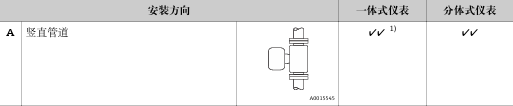
1.2 Installation Orientation for High/Low-Temperature Media
Risk of overheating of electronic components! When the fluid temperature exceeds 200°C (392°F), installation orientation B is prohibited for wafer-type meters (Prowirl D) with nominal diameters DN 100 (4") and DN 150 (6"). For media at different temperatures, the following installation orientations are recommended:
| Medium Condition | Recommended Installation Orientation | Description |
|---|---|---|
| High-temperature medium (such as steam or temperature >200°C) | C or D | Avoid overheating of electronic components |
| Low-temperature medium (such as liquid nitrogen) | B or D | Prevent the effects of condensation or icing |
| With the "wet steam detection/measurement" option | C | Ensure accurate wet steam measurement |
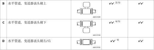
1.3 Key Installation Checklist
- Consistent flow direction: The sensor arrow must be in the same direction as the medium flow.
- Full pipe condition: Avoid non-full pipe when measuring liquids; vertical pipeline flow from bottom to top is preferred.
- Temperature suitability: Select the installation orientation according to the table above for high- or low-temperature media.
- Diameter limitation: Orientation B is prohibited for DN 100/150 wafer-type meters at high temperatures.
2. Summary
Following the above installation specifications can effectively avoid measurement errors and equipment damage. If the operating conditions are special, be sure to refer to the official E+H manual or consult technical support.