
Wiring Guide for Temperature Transmitter TMT142B
The temperature transmitter TMT142B is a commonly used signal conversion device in industrial sites, and its wiring method varies depending on the sensor type. Correct wiring is the foundation for ensuring measurement accuracy and stable operation. This article introduces the wiring methods for thermocouples and RTDs step by step.
Input 1 Wiring Instructions
Input 1 of the TMT142B supports multiple sensor types, including thermocouples and RTDs (two-wire, three-wire, and four-wire systems). Before wiring, please confirm the sensor type and refer to the following steps.
Thermocouple Wiring
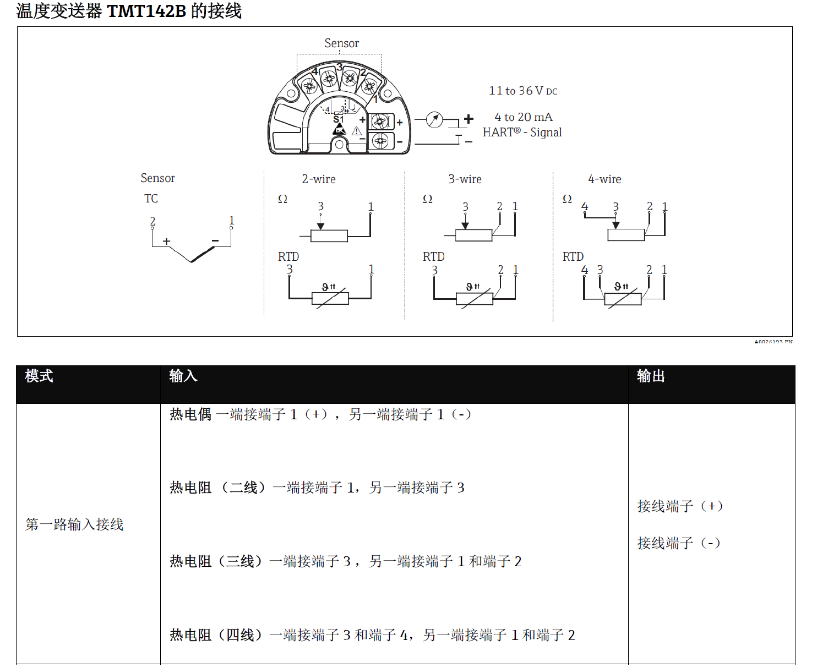
- Connect the positive pole (+) of the thermocouple to terminal 1.
- Connect the negative pole (-) of the thermocouple to terminal 1 (note: the same terminal, but polarity must be distinguished).
Please ensure the polarity is correct, otherwise measurement errors will occur.
RTD Wiring
Depending on the wiring system, RTDs are connected as follows:
| RTD Type | Wiring Method |
|---|---|
| Two-wire | One end to terminal 1, the other end to terminal 3 |
| Three-wire | One end to terminal 3, the other end to terminal 1 and terminal 2 |
| Four-wire | One end to terminal 3 and terminal 4, the other end to terminal 1 and terminal 2 |
Three-wire and four-wire systems can effectively eliminate the influence of lead resistance and improve measurement accuracy.
Wiring Diagram
The following figure shows the terminal arrangement and typical wiring methods of the TMT142B for reference during installation.
Precautions
- Disconnect the power supply before wiring to ensure safety.
- Use a suitable screwdriver to tighten the terminals to avoid loose connections.
- For thermocouples, compensation wires must be used.
- For RTDs, it is recommended to use a three-wire or four-wire system to reduce errors.
Following the above steps ensures correct wiring of the TMT142B temperature transmitter and achieves accurate temperature measurement.