
TMT72 Temperature Transmitter Wiring Overview
The TMT72 temperature transmitter adopts a modular installation design and supports multiple temperature sensor inputs, including thermocouples and RTDs. Correct wiring is the key to ensuring measurement accuracy and stable operation. This article introduces its wiring methods by type.
Detailed Wiring Methods
Thermocouple Wiring
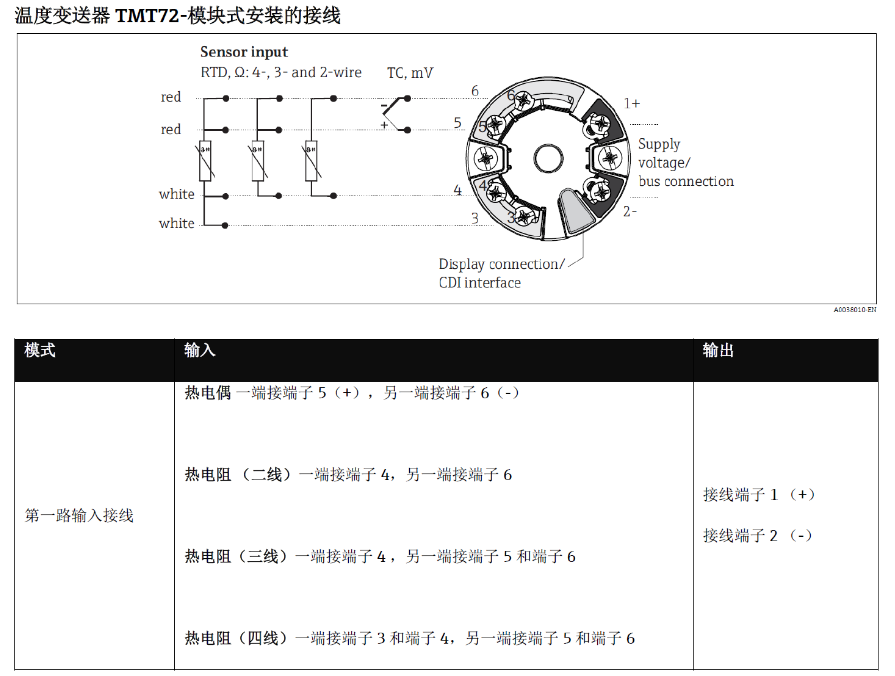
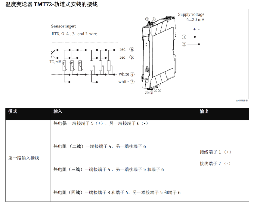
- Connect the positive pole of the thermocouple to terminal 5(+), and the negative pole to terminal 6(-).
RTD Wiring
RTD wiring methods differ depending on the wire configuration, as follows:
- 2-wire RTD: Connect one end to terminal 4, and the other end to terminal 6.
- 3-wire RTD: Connect one end to terminal 4, and the other end to terminal 5 and terminal 6.
- 4-wire RTD: Connect one end to terminal 3 and terminal 4, and the other end to terminal 5 and terminal 6.
When wiring, please ensure the terminals are tightened to avoid measurement errors caused by loose connections.
Wiring Diagram
The following are wiring diagrams for the TMT72 temperature transmitter for reference:
Wiring Precautions
- Be sure to perform wiring operations with the power disconnected to ensure safety.
- Select the correct wire configuration according to the sensor type and connect to the corresponding terminals.
- Use appropriate wire gauges and shielded cables to reduce interference.
- After wiring is completed, check whether all terminals are secure to avoid looseness.
Summary
Correct wiring is the foundation for reliable operation of the TMT72 temperature transmitter. Following the above wiring methods can effectively improve measurement accuracy and system stability. If you have any questions, please refer to the product manual or contact technical support.