
TMT84 Temperature Transmitter Wiring Overview
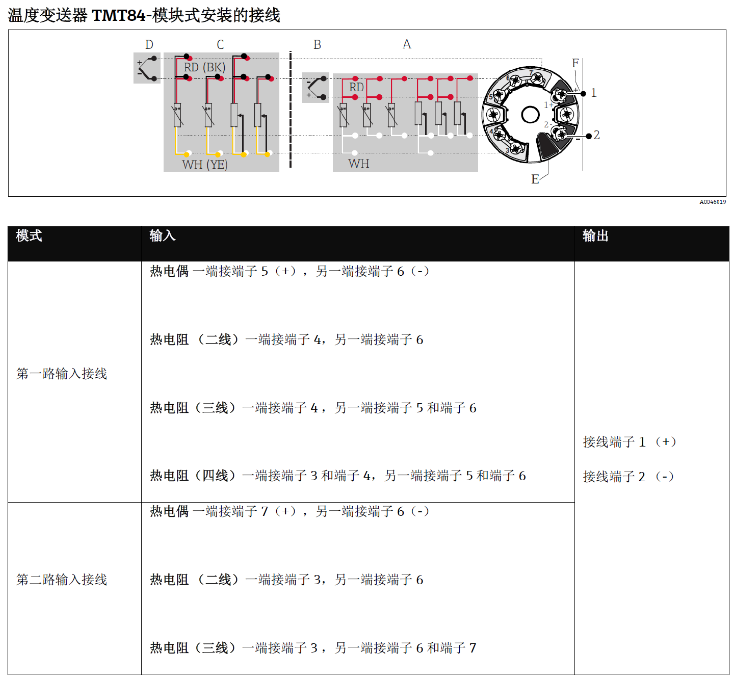
The TMT84 temperature transmitter features a modular installation design and supports both thermocouple and RTD sensor inputs. Correct wiring is the prerequisite for ensuring measurement accuracy and stable operation. This article introduces its terminal wiring methods by type, with wiring diagrams attached.
Thermocouple Wiring Method
The thermocouple signal is a millivolt-level voltage and must be connected directly to the corresponding terminals of the transmitter.
- Connect the thermocouple positive pole to terminal 5 (+)
- Connect the thermocouple negative pole to terminal 6 (-)
Please ensure correct polarity; otherwise, the measured value will be reversed or fluctuate.
RTD Wiring Method
RTDs are classified into 2-wire, 3-wire, and 4-wire types based on the number of lead wires. The wiring methods differ, and accuracy increases accordingly.
2-Wire RTD
- Connect one end of the RTD to terminal 4
- Connect the other end to terminal 6
The 2-wire connection is simple, but lead wire resistance introduces errors, making it suitable for applications with low accuracy requirements.
3-Wire RTD
- Connect one end of the RTD to terminal 4
- Connect the other end to terminal 5 and terminal 6
The 3-wire connection compensates for lead wire resistance and is the most commonly used wiring method in industrial sites.
4-Wire RTD
- Connect one end of the RTD to terminal 3 and terminal 4
- Connect the other end to terminal 5 and terminal 6
The 4-wire connection completely eliminates the effect of lead wire resistance and is suitable for high-precision measurement.
Comparison and Selection of Wiring Methods
| Sensor Type | Wiring Terminals | Accuracy | Application Scenario |
|---|---|---|---|
| Thermocouple | 5(+), 6(-) | Medium | High-temperature measurement |
| 2-Wire RTD | 4, 6 | Low | Short distance, low accuracy |
| 3-Wire RTD | 4, 5, 6 | High | General industrial sites |
| 4-Wire RTD | 3, 4, 5, 6 | High | Laboratory, high precision |
Wiring Diagram
The figure below shows the terminal arrangement and wiring methods of the TMT84 for reference during installation.
Wiring Precautions
- Before wiring, confirm that the power supply is disconnected to avoid short circuits or damage to the transmitter.
- Use shielded cables and ensure that the shield is grounded at one end only to reduce interference.
- Terminal screws must be tightened to prevent poor contact that could cause signal jumps.
- For 3-wire and 4-wire connections, the lead wire resistances should be as consistent as possible.
Following the above wiring specifications ensures the long-term stable operation of the TMT84 temperature transmitter and improves measurement accuracy.