
1. Wiring Steps
1. Connecting Analog Sensors
Correct wiring is the foundation for the transmitter to work properly. Please follow the steps below to connect an analog sensor:
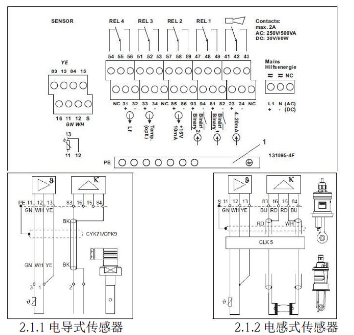
- Affix the corresponding wiring diagram provided to the terminal block.
- Connect the green, white, and yellow temperature wires to terminals 11, 12, and 13 respectively.
- For conductive sensors, connect the measurement signal to terminals 83 (main wire) and 84 (secondary wire); for inductive sensors, connect the measurement signal by color: connect the wire-color to core-color wire to terminal 83, the red-to-red wire to terminal 16, the white-to-blue wire to terminal 84, and the white-to-red wire to terminal 15.
- Connect the outer shield of the conductive sensor cable to the "PE" terminal, and the outer shield of the inductive sensor cable to the "S" terminal.
- Do not connect terminals marked "NC" or unmarked terminals.
- Connect the 220VAC power supply to terminals L1 and N; connect the 24VDC power supply to terminals + and -.
- Connect the first current output (conductivity) to terminals 31 and 32, and the second current output (temperature, optional) to terminals 33 and 34. The current output is an active output.
2. Connecting Memosens Digital Sensors
Memosens digital sensors use a four-wire connection. The specific steps are as follows:
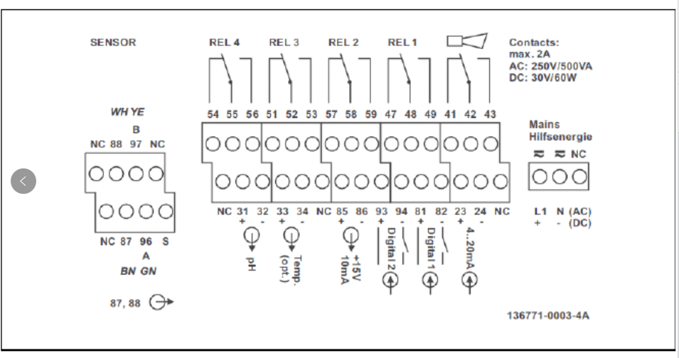
- Affix the corresponding wiring diagram provided to the terminal block.
- Connect the brown, white, green, and yellow cable wires to terminals 87, 88, 96, and 97 respectively.
- Do not connect terminals marked "NC" or unmarked terminals.
- Connect the 220VAC power supply to terminals L1 and N; connect the 24VDC power supply to terminals + and -.
- Connect the first current output (conductivity) to terminals 31 and 32, and the second current output (temperature, optional) to terminals 33 and 34. The current output is an active output.
Note: Ensure all cable glands are tightened and sealed to maintain the protection rating.
2. Key Functions
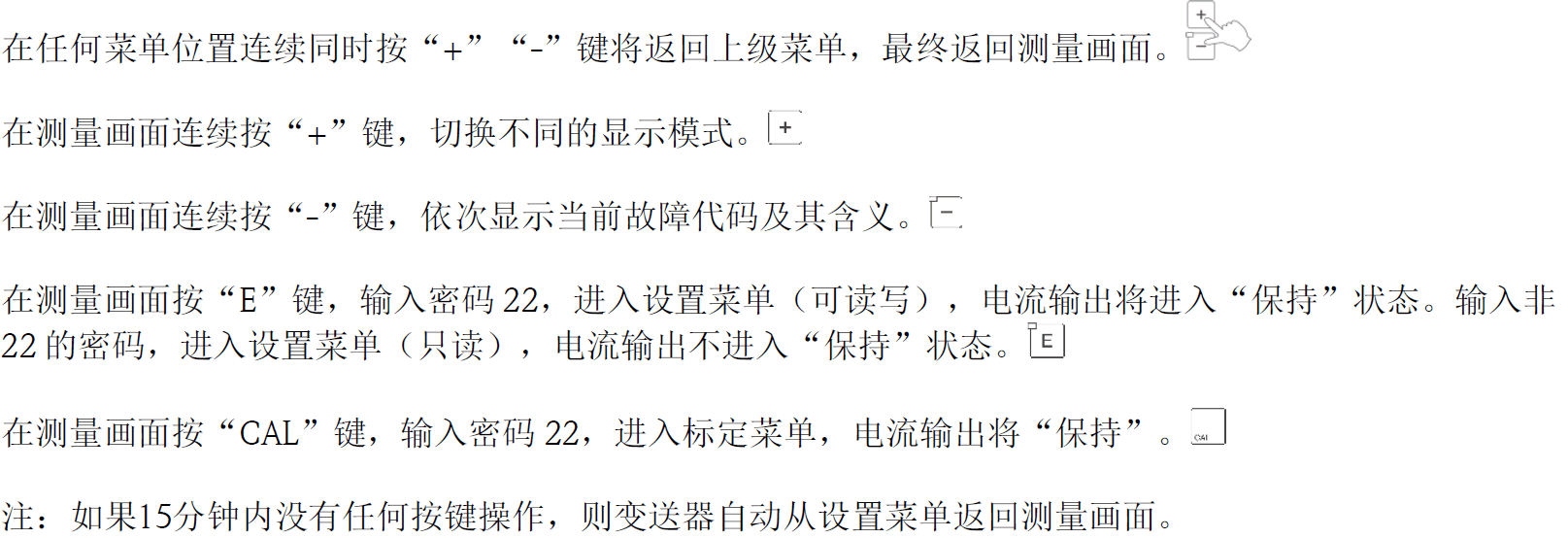
The transmitter panel keys are used for menu navigation and parameter setting. The functions of each key are as follows:
3. Parameter Settings
1. Sensor Settings
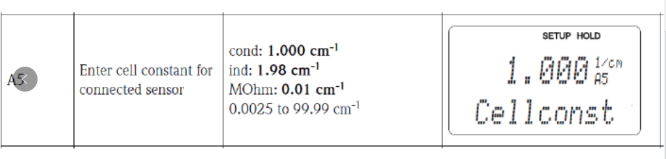
The sensor is shipped with a calibration certificate, and the electrode constant must be entered. The steps are as follows:
- Press the "E" key and enter the password "22".
- In the "A5" menu under the "SETUP 1" menu, enter the electrode constant from the calibration certificate.
2. Range Settings
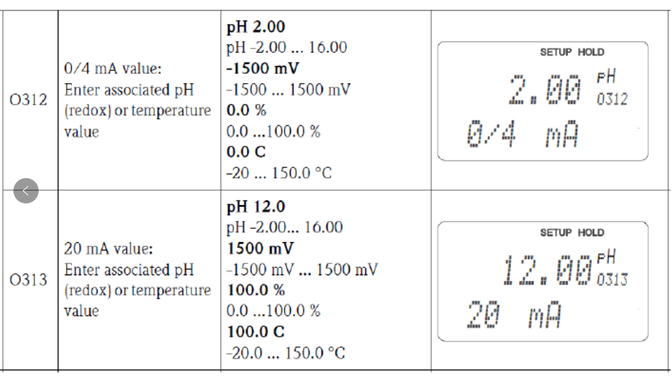
In the "Current Output" menu, set the 4-20mA corresponding range. In 01, select the current output channel. For dual-channel output, there are OUT1 and OUT2 options; for single-channel output, proceed directly to the next item. OUT1 is used as the conductivity current output; OUT2 is used as the temperature current output.
3. Restoring Transmitter Factory Settings
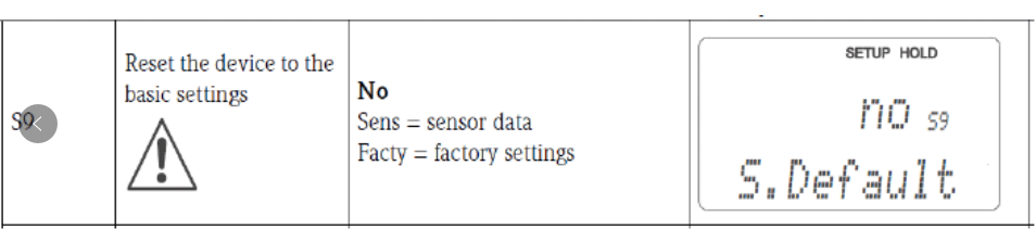
To restore factory settings, in the "S9" menu under the "Service" menu, select "Facty" to reset the transmitter.
4. Calibration Methods
1. Air Calibration (Inductive Sensors Only)
Before starting calibration, remove the sensor from the medium, clean it, and dry it. Press the "CAL" key and enter the password "22". Complete the calibration under the "Calibration" menu:
- Enter the "C1" menu and select the first option, i.e., air calibration.
- Enter the "C111" menu, observe the measured value in air, and press the "E" key to confirm and start calibration.
- Enter the "C112" menu to view the air calibration value; in the "C114" menu, select whether to save the calibration data or recalibrate.
2. Electrode Constant Calibration
Press the "CAL" key and enter the password "22". Complete the calibration under the "Calibration" menu:
- Enter the "C1" menu and select the second option, i.e., electrode constant calibration.
- Enter the "C121" and "C122" menus to input the reference temperature for calibration (factory default 25°C) and the temperature compensation coefficient (factory default 2.1%/K).
- Enter the "C123" menu, input the conductivity value of the calibration solution, and press the "E" key to confirm and start calibration.
- Enter the "C124" menu to observe the calibrated electrode constant, and record this value.
- The "C125" menu will display whether the calibration passed.
- In the "C126" menu, select whether to save the calibration data or discard and recalibrate.