
I. SM100 Series HART Smart Converter Product Introduction
1.1 Product Introduction
The SM100 series HART smart converter is a product developed using an ARM microprocessor, a dedicated HART protocol modem chip, and extensive practical experience. It is designed according to industrial product requirements and has very high reliability and stability.
The smart converter is equipped with standard RS232 interfaces and RS485 interfaces, and can perform transparent data transmission with HART protocol smart instruments, or convert to the MODBUS_RTU protocol to read data, ensuring real-time data transmission.
The HART protocol uses the Bell202 Frequency Shift Keying (FSK) standard, superimposing a modulated digital signal on the 4–20 mA signal, so that HART protocol instruments allow bidirectional data communication without interfering with the 4–20 mA analog signal. The SM100 series smart converter is a smart converter that performs bidirectional modulation and demodulation of digital signals and analog signals.
1.2 Product Features
- Equipped with standard RS232 and RS485 communication interfaces, allowing parameter configuration and modification of communication baud rate and parity bit. It is independent of the 1200 communication speed on the HART bus, thereby improving the operating speed of the entire system.
- Uses an industrially common modular housing, facilitating installation and debugging.
- Equipped with dedicated configuration software, which can configure parameters for the SM100 series smart converter and, through the smart converter, communicate data with HART protocol smart instruments.
- Supports the standard MODBUS_RTU protocol.
- Supports simultaneous connection to multiple HART protocol smart instruments.
- Supports various special HART protocol smart instruments and can customize commands to read special HART instruments.
1.3 Main Parameters
| Parameter Name | Specification Index |
|---|---|
| Power input voltage | DC 12–24V, power ripple must not exceed 200mA, current must provide 100mA |
| Housing dimensions | Length 134mm × Width 71mm × Height 43mm |
| Operating ambient temperature | -20℃ to +80℃ |
| Relative humidity | 10% to 80% |
For more information, it is recommended to consult relevant experts or refer to the product manual. Large stock available, welcome to purchase.
II. Interface Definitions and Indicator Light Descriptions
2.1 Terminal Block Definitions
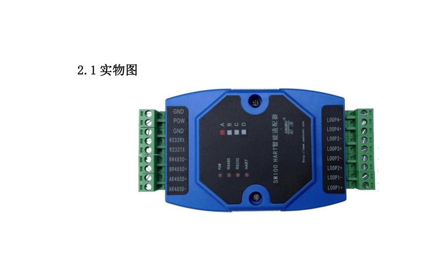
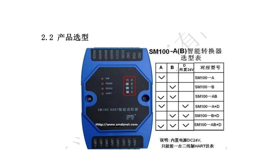
- GND.POW: Power interface terminal block; POW connects to the positive pole of the power supply, GND connects to the negative pole of the power supply.
- GND, R232RX, R232TX: RS232 communication interface terminal block.
- BR485D-, BR485D+: RS485 communication interface B terminal block.
- AR485D-, AR485D+: RS485 communication interface A terminal block.
- LOOP1+, LOOP1- to LOOP4+, LOOP4-: A total of four groups of HART instrument communication interface terminal blocks.
2.2 Indicator Light Descriptions
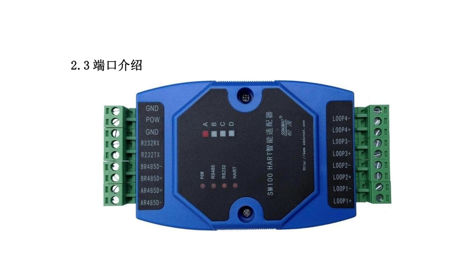
- POW power indicator: Constantly on after power is connected.
- RS485 communication indicator: Flashes when data exchange occurs on the RS485 serial port.
- RS232 communication indicator: Flashes when data exchange occurs on the RS232 serial port.
- HART communication indicator: Flashes when data exchange occurs between the HART converter and HART instruments.
III. HART Protocol Instrument Wiring and Debugging
3.1 Difference Between Two-Wire and Four-Wire HART Protocol Instruments
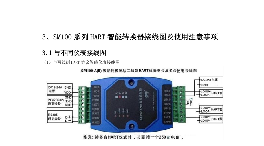
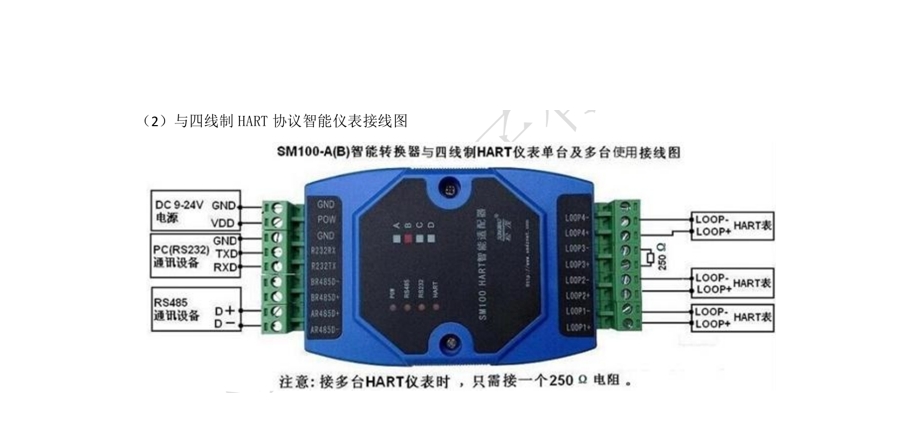
- Four-wire HART protocol instruments: Powered separately; their power lines and 4–20 mA input/output lines are separate.
- Two-wire HART protocol instruments: The power lines and 4–20 mA input/output lines share the same two wires.
3.2 Debugging Steps for Connecting the HART Smart Converter to Multiple HART Protocol Instruments
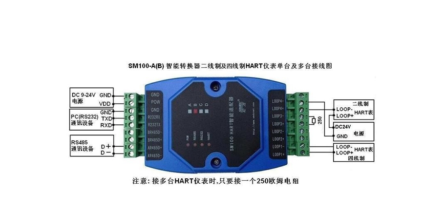
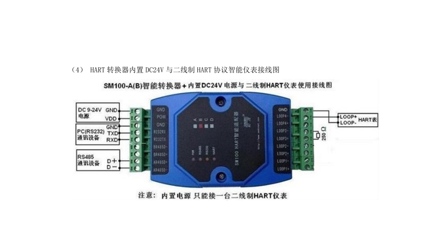
- Connecting 1 HART protocol smart instrument: The HART address defaults to 0 and does not need to be modified.
- Connecting 4 HART protocol smart instruments: The HART addresses must be changed to 1, 2, 3, 4. At this time, the current output by all HART sensors is 4 mA, and only one 250Ω resistor needs to be connected.
- Connecting 8 HART protocol smart instruments: The HART addresses must be changed to 1, 2, 3, 4, 5, 6, 7, 8. At this time, the current output by all HART sensors is 4 mA, and only one 250Ω resistor needs to be connected.
- When using a USB/RS232 converter and then connecting an RS232/RS485 converter: The RS232/RS485 converter needs to be connected to a DC5V power supply.
- When using the Siemens PLC programming cable USB-PPI (USB-RS485 cable): Pin 3 is D+, and pin 8 is D-.
IV. Configuration Software Function Introduction and Operation Steps
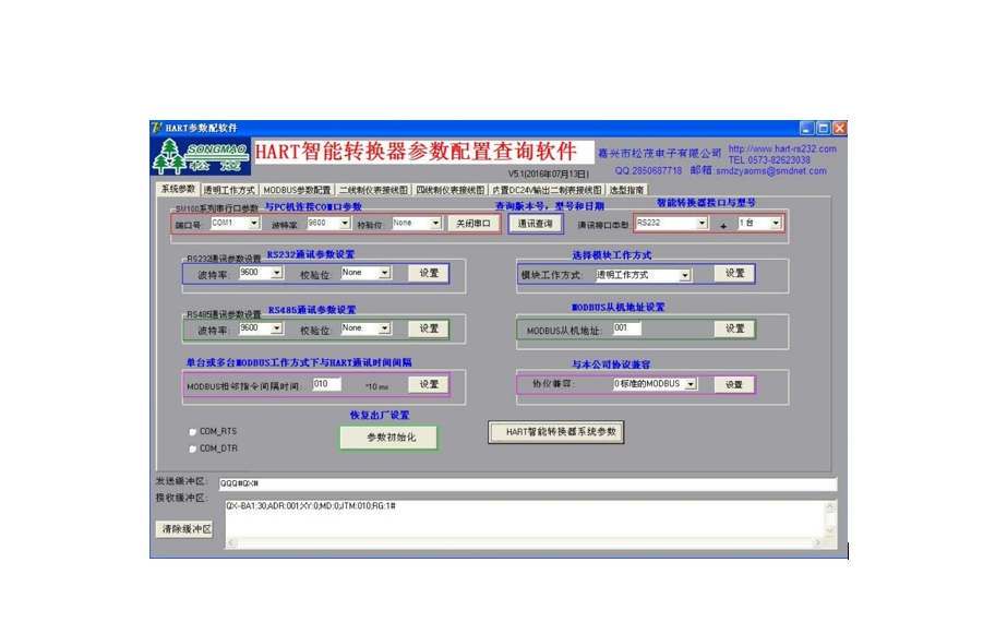
4.1 System Parameter Interface Function Introduction
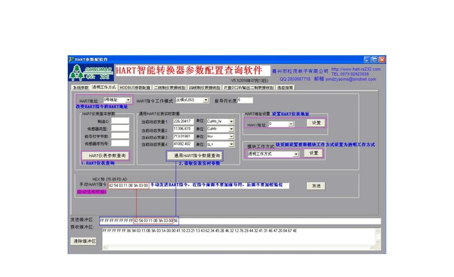
4.2 Transparent Working Mode Interface Function Introduction
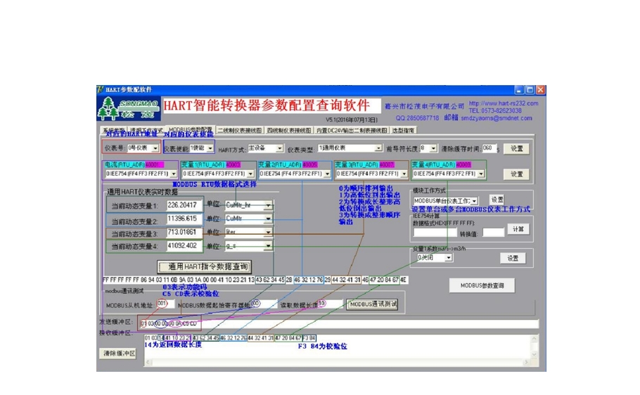
4.3 General HART Protocol Interface Function Introduction
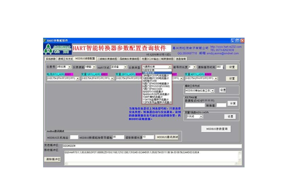
4.4 Special HART Protocol Interface Function Introduction
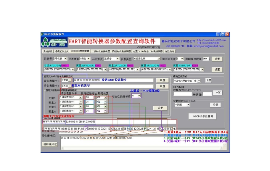
4.5 Custom HART Protocol Interface Function Introduction
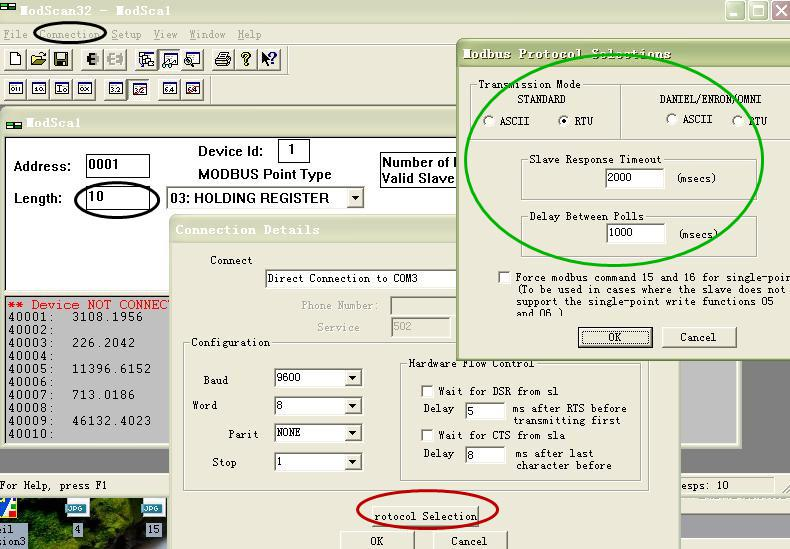
4.6 Reading Data with ModScan32 Test Software
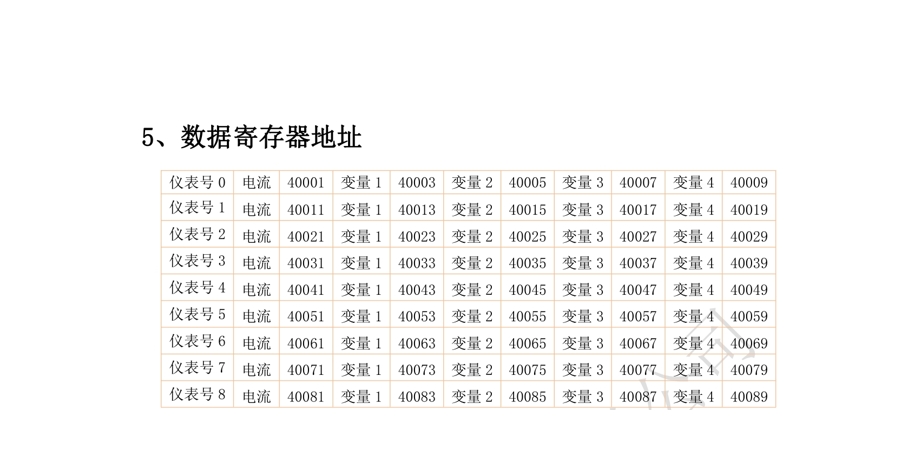
V. Data Register Addresses
VI. Precautions for Using the SM100 Series HART Smart Converter
- Please read the manual carefully before use.
- Confirm whether the power supply meets the equipment's working requirements.
- Check whether the distance to the HART instrument equipment is greater than 200m. If it exceeds this range, please use thicker wires and add shielded cable. When using shielded wire, please ground one end.
- Check whether there are large inductive loads nearby. These cause severe signal interference, and appropriate shielding measures should be taken.