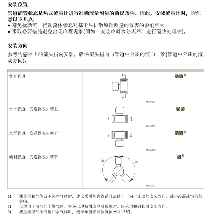
1. Installation Position
Correct installation position is crucial for measurement accuracy. Please ensure the flowmeter is installed in a location with a sufficiently long straight pipe section, and avoid vibration and strong electromagnetic interference.
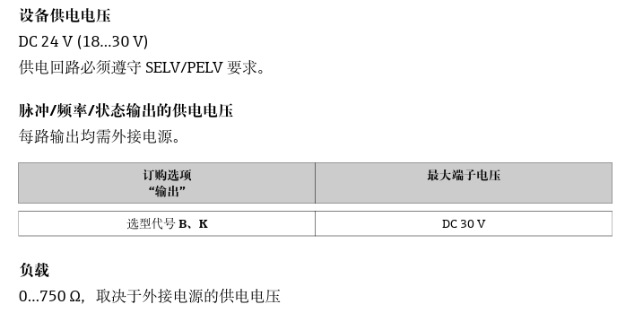
2. Power Supply Requirements
The power supply voltage must match the voltage marked on the nameplate. Please be sure to check the nameplate information to avoid equipment damage caused by voltage mismatch.
2.1 Terminal Assignment
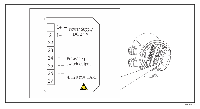
The electrical connection diagram of the terminals is located on the nameplate of the electronics module. Please wire correctly according to the diagram to ensure that the power supply and signal lines are connected properly.
3. Operation Menu
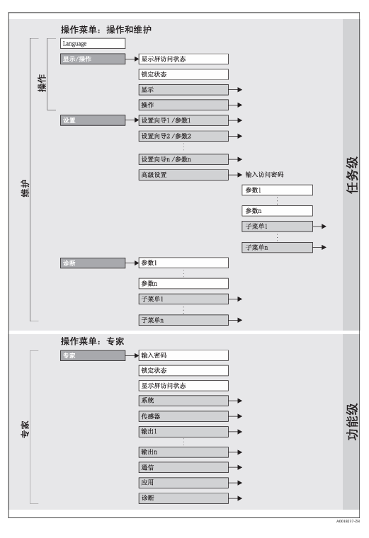
The operation menu is the main interface for parameter setting and viewing measured values. All configuration options can be accessed through the menu.
3.1 Operation Display
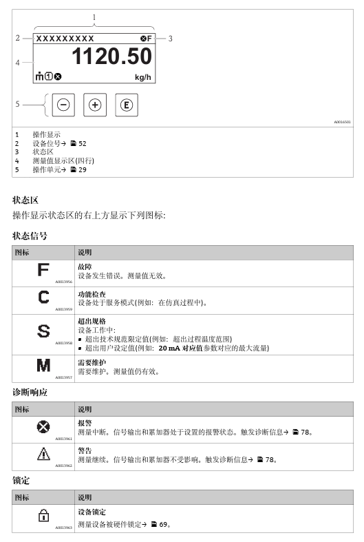
The display provides real-time measured values and menu navigation information. Familiarity with the display interface helps to operate quickly.
3.2 Editing Diagram
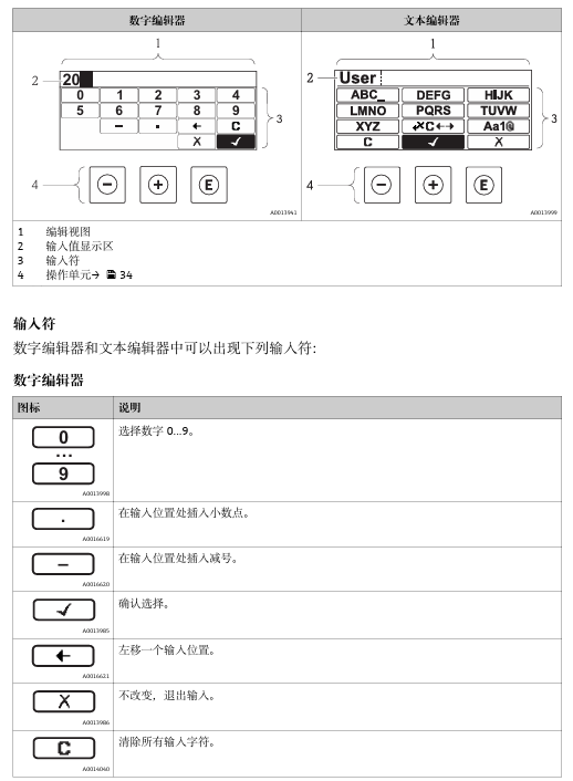
The editing diagram shows the process of parameter modification. Please follow the steps in the diagram to edit parameters.
4. Commissioning
Commissioning is a key step to ensure accurate measurement of the flowmeter. The following commissioning steps must be performed in order.
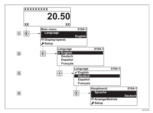
4.1 Setting the Operating Language
Factory setting: English or the local language ordered. The operating language can be changed as needed.
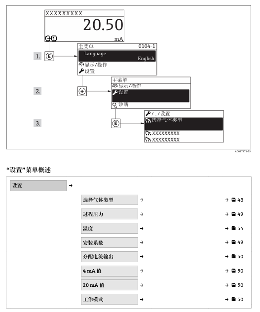
4.2 Setting the Measuring Device
The "Setup" menu and its setup wizard contain all parameters required for standard operation. Please configure them in sequence.
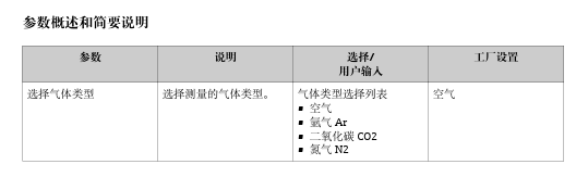
4.3 Selecting Gas Type
Menu path: "Setup" menu → Select gas type. Select the correct gas according to the actual measuring medium.
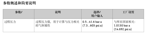
4.4 Setting Process Pressure
Menu path: "Setup" menu → Process pressure. Enter the actual process pressure value.
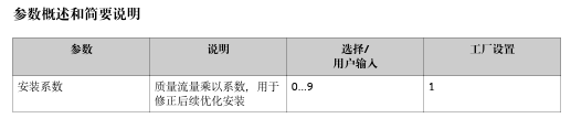
4.5 Determining Installation Factor
Menu path: "Setup" menu → Installation factor. Set the appropriate factor according to the installation conditions.
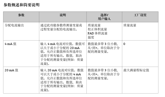
4.6 Setting Current Output
Menu path: "Setup" menu → Assign current output; "Setup" menu → 4 mA value; "Setup" menu → 20 mA value. Configure the current output range.
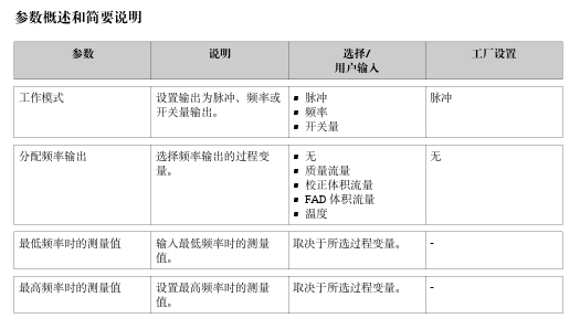
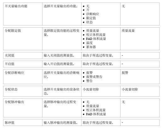
4.7 Setting Pulse/Frequency/Switch Output
Menu path:
- "Setup" menu → Operating mode
- "Setup" menu → Assign frequency output
- "Setup" menu → Switch output function
- "Setup" menu → Assign pulse output