
CPM253/223 Transmitter pH/ORP Basic Commissioning Guide
The CPM253/223 transmitter is a commonly used instrument in industrial pH/ORP measurement. Correct installation, wiring, and commissioning are key to ensuring measurement accuracy and long-term stable operation of the instrument. This article is intended for engineering and technical personnel and procurement staff, and systematically introduces its installation, wiring, and basic operation.
1. Installation
The CPM253 transmitter supports three installation methods: wall mounting, pipe mounting, and climate protection installation. Users can choose the appropriate method according to the site environment.
1.1 Wall Mounting
Wall mounting is the simplest method, using the two mounting holes on the back of the transmitter to fix it directly to the wall.
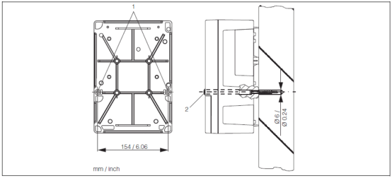
The two Ø6 holes at position 1 are fixed to the wall with screws. At the factory, these two holes are plugged with colored plugs (position 2), which must be removed before installation.
1.2 Pipe Mounting
Pipe mounting is suitable for vertical or horizontal pipes, using the four M5 screw holes on the back of the transmitter for fixation.
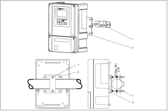
During installation, use the four M5 screw holes on the back of the transmitter (position 2). The maximum pipe diameter is Ø60. Pipe mounting requires additional ordering of mounting accessories.
1.3 Climate Protection Installation
For outdoor open-air environments, it is recommended to use a climate protection cover to protect the instrument from sunlight and rain.
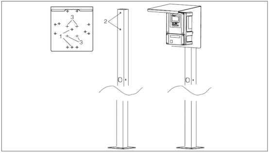
Note: The climate protection cover must be ordered separately as an accessory. If the transmitter is installed outdoors in an open-air environment, it is recommended to use a climate protection cover to protect the instrument.
1.4 Sensor Installation
The installation angle of the sensor directly affects measurement accuracy, and the installation requirements must be strictly followed.
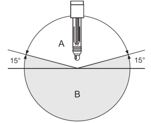
For the vast majority of pH sensors, the horizontal tilt angle of installation must be at least 15°. Inverted installation of the sensor is prohibited. IsFET sensors and CPS71(D)-BU sensors are exceptions.
- A: Permitted installation tilt angle (≥15°)
- B: Prohibited installation tilt angle (inverted or insufficient tilt)
2. Wiring
The CPM253 transmitter can be connected to analog sensors or Memosens digital sensors. Before wiring, confirm that the power supply is disconnected and operate according to the wiring diagram provided with the unit.
2.1 Connecting Analog Sensors
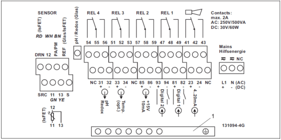
- Affix the corresponding wiring diagram provided with the unit to the terminal block.
- Connect the green, white, and yellow temperature wires to terminals 11, 12, and 13 respectively.
- Standard analog sensor (using CPK9 cable): the core wire and black shield wire of the coaxial cable represent the measurement and reference signals respectively, and are connected to the "pH" and "REF" terminals respectively; the brown equipotential wire is connected to the "PA/PM" terminal.
- IsFET analog sensor (using CPK12 cable): the core wire and colored shield wire of the coaxial cable represent the measurement and reference signals respectively, and are connected to the "SRC" and "REF" terminals respectively; the red wire is connected to the DRN terminal; the brown equipotential wire is connected to the "PA/PM" terminal.
- The outer shield of the glass sensor cable is connected to the "S" terminal; the outer shield of the IsFET sensor cable is connected to the PE terminal, and the PE terminal is grounded.
- Terminals marked "NC" and unmarked terminals are not connected.
- Connect the 220VAC power supply to the L1 and N terminals; connect the 24VDC power supply to the + and - terminals.
- Connect the first current output (pH) to terminals 31 and 32, and the second current output (temperature, optional) to terminals 33 and 34. The current output is an active output.
2.2 Connecting Memosens Digital Sensors
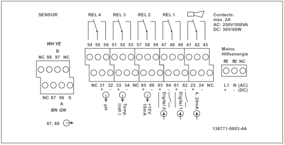
- Affix the corresponding wiring diagram provided with the unit to the terminal block.
- Connect the brown, white, green, and yellow cable wires to terminals 87, 88, 96, and 97 respectively.
- Terminals marked "NC" and unmarked terminals are not connected.
- Connect the 220VAC power supply to the L1 and N terminals; connect the 24VDC power supply to the + and - terminals.
- Connect the first current output (pH) to terminals 31 and 32, and the second current output (temperature, optional) to terminals 33 and 34. The current output is an active output.
Note: Ensure that all cable glands are tightened and sealed to ensure the protection rating.
3. Key Functions
Familiarity with key functions is the basis for parameter setting and daily operation. The following introduces basic key functions, keypad locking, and relay operation.
3.1 Basic Key Function Description
- At any menu position, pressing the "." and ".." keys simultaneously continuously will return to the previous menu, and ultimately return to the measurement screen.
- On the measurement screen, pressing the "+" key continuously switches between different display modes.
- On the measurement screen, pressing the "-" key continuously displays the previous error codes and their information in sequence.
- On the measurement screen, pressing the "E" key and entering password 22 enters the setup menu (read/write). The power output will enter the "hold" state.
- Entering a variant of password 22 enters the setup menu (read-only). The current output does not enter the "hold" state.
- On the measurement screen, pressing the "CAL" key and entering password 22 enters the calibration menu, and the current output will be "held".
- If no key is operated within 15 minutes, the transmitter automatically returns from the setup menu to the measurement screen.
[Click image to enlarge]
3.2 Keypad Locking and Unlocking
To prevent misoperation, the keypad can be locked. After locking, all settings are read-only, and the password always displays 0990 and cannot be modified.
- Lock: Press the "+" key and the "E" key simultaneously for more than 3s.
- Unlock: Press the "CAL" key and the "-" key simultaneously for more than 3s, and the password displays 0.
[Click image to enlarge]
3.3 Relay Operation
On the measurement screen, use the AUTO key to switch the relay between "automatic mode" and "manual mode".
- Manual mode: Press the REL key to switch between different relays, press the "+" key to close the relay, and press the "-" key to open the relay.
- Automatic mode: Press the REL key to read the relay's set point or reset point. Press the "+" key to switch to the next relay, and press the REL key to return to the measurement screen.
[Click image to enlarge]