
CLM253/223 Transmitter Conductivity Commissioning Guide
The CLM253/223 transmitter is a commonly used instrument in industrial conductivity measurement. Based on original manufacturer materials, this article systematically organizes its installation, wiring, keypad operation, settings, calibration, and troubleshooting steps to help engineering technicians quickly complete commissioning.
1. Installation Methods
The CLM253 supports three installation methods, which can be selected according to the on-site environment.
1.1 Wall Mounting
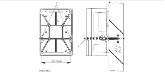
Use the two Ø6 holes at position 1 on the back of the transmitter to secure it to the wall with screws. At the factory, these two holes are plugged with black plugs (position 2), which must be removed before installation.
[Click image to enlarge]
1.2 Pipe Mounting
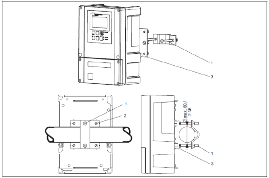
Supports vertical or horizontal pipe mounting. Use the four M5 threaded holes on the back of the transmitter (position 2). The maximum pipe diameter is Ø60. Pipe mounting requires additional mounting accessories to be ordered separately.
[Click image to enlarge]
1.3 Weather Protection Cover Installation
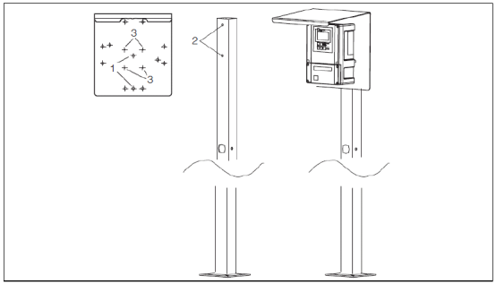
The weather protection cover must be ordered separately as an accessory. If the transmitter is installed outdoors in an open environment, it is recommended to use a weather protection cover to protect the instrument.
[Click image to enlarge]
2. Wiring Methods
Before wiring, confirm that the power supply is disconnected and operate according to the wiring diagram provided with the unit.
2.1 Connecting Analog Sensors
[Click image to enlarge]
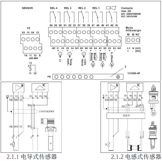
- Attach the corresponding wiring diagram provided with the unit to the terminal block.
- Connect the green, white, and yellow temperature wires to terminals 11, 12, and 13 respectively.
- For conductive sensors, connect the measurement signal to terminals 83 (main line) and 84 (secondary line). For inductive sensors, the measurement signal wiring is: red-blue wire to terminal 83, red-red wire to terminal 16, white-blue wire to terminal 84, white-red wire to terminal 15.
- Connect the outer shield of the conductive sensor cable to the "PE" terminal, and the outer shield of the inductive sensor cable to the "S" terminal.
- Terminals marked "NC" and unmarked terminals are not connected.
- Connect 220VAC power to terminals L1 and N; connect 24VDC power to terminals + and -.
- Connect the first current output (conductivity) to terminals 31 and 32, and the second current output (temperature, optional) to terminals 33 and 34. The current output is an active output.
2.2 Connecting Memosens Digital Sensors
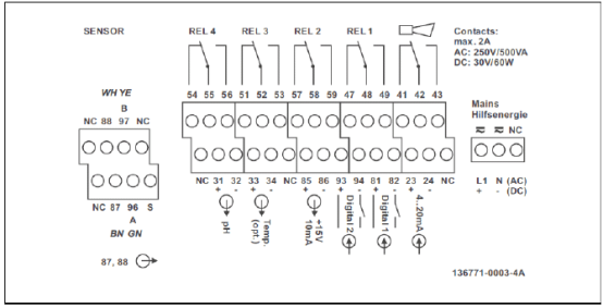
[Click image to enlarge]
- Attach the corresponding wiring diagram provided with the unit to the terminal block.
- Connect the brown, white, green, and yellow cable wires to terminals 87, 88, 96, and 97 respectively.
- Terminals marked "NC" and unmarked terminals are not connected.
- Connect 220VAC power to terminals L1 and N; connect 24VDC power to terminals + and -.
- Connect the first current output (conductivity) to terminals 31 and 32, and the second current output (temperature, optional) to terminals 33 and 34. The current output is an active output.
Note: Ensure that all cable glands are tightened and sealed.
3. Keypad Functions
3.1 Basic Keypad Function Description
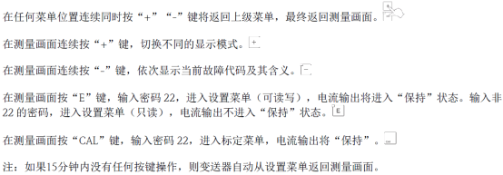
[Click image to enlarge]
3.2 Keypad Lock and Unlock

[Click image to enlarge]
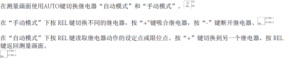
[Click image to enlarge]
4. Parameter Settings
4.1 Sensor Settings
Find the sensor's factory calibration certificate. Press the "E" key and enter password "22". In the "A5" menu under the "SETUP1" menu, enter the electrode constant from the calibration certificate.
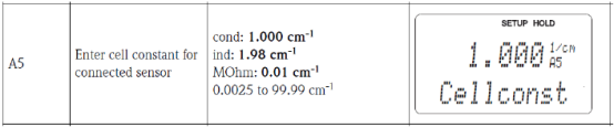
[Click image to enlarge]
4.2 Range Settings
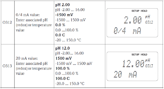
In the "Current Output" menu, set the range corresponding to 4-20mA. In O1, select the current output channel. For dual-channel output instruments, there are OUT1 and OUT2 options; for single-channel output, proceed directly to the next item. OUT1 serves as the conductivity current output; OUT2 serves as the temperature current output.
[Click image to enlarge]
4.3 Transmitter Reset
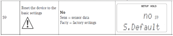
In the "S9" menu under the "Service" menu, select "Facty" to reset the transmitter.
[Click image to enlarge]
5. Calibration Steps
5.1 Air Calibration (Inductive Sensors Only)
Before starting calibration, remove the sensor from the medium, clean and dry it. Press the "CAL" key and enter password "22". Complete calibration under the "Calibration" menu.
- Enter the "C1" menu and select the first option, i.e., air calibration.
- Enter the "C111" menu, observe the measurement value in air, and press the "E" key to confirm and start calibration.
- Enter the "C112" menu to view the air calibration value.
- The "C113" menu will display whether the calibration passed.
- The "C114" menu allows you to choose whether to save the calibration data, discard it, or recalibrate.
5.2 Electrode Constant Calibration
Press the "CAL" key and enter password "22". Complete calibration under the "Calibration" menu.
- Enter the "C1" menu and select the second option, i.e., electrode constant calibration.
- Enter the "C121" and "C122" menus to input the reference temperature (factory default 25°C) and temperature compensation coefficient (factory default 2.1%/K) for calibration.
- Enter the "C123" menu, input the conductivity value of the calibration solution, and press the key to confirm and start calibration.
- Enter the "C124" menu to observe the calibrated electrode constant and record this value.
- The "C125" menu will display whether the calibration passed.
- The "C126" menu allows you to choose whether to save the calibration data, discard it, or recalibrate.
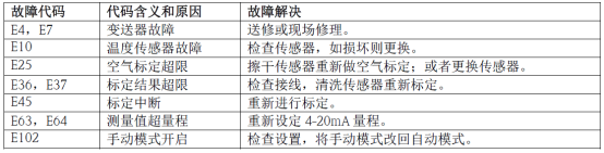
6. Common Fault Codes
[Click image to enlarge]