CM42 Transmitter Conductivity Basic Commissioning Guide
The CM42 transmitter is specifically designed for conductivity measurement. Its commissioning process includes installation, wiring, key operations, parameter setting, calibration, and troubleshooting. Based on official documentation, this article systematically outlines the commissioning steps to help engineering technicians and procurement personnel get started quickly.
1. Installation Methods
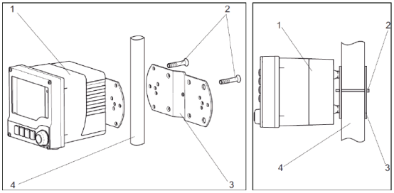
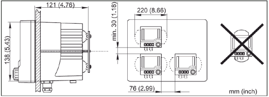
The CM42 has 4 installation methods, which can be selected according to site conditions.
1.1 Horizontal Pipe Installation
1.2 Vertical Pipe Installation
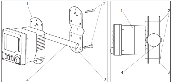
Note: Horizontal and vertical pipe installations require additional ordering of installation accessories.
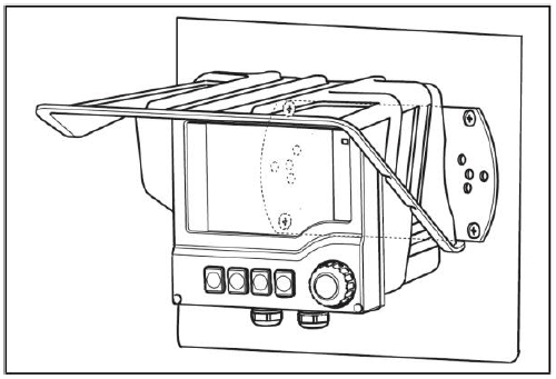
1.3 Wall Mounting (Optional Weather Protection Cover)
1.4 Panel Mounting
2. Wiring
Note: Ground the plastic housing and cable as shown in the figure below.
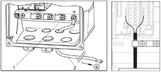
2.1 Power/Signal Wiring
2.1.1 One Current Output and Two Current Outputs (Optional)
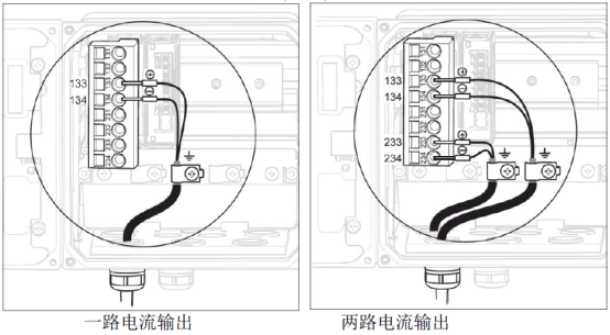
Note: The allowable supply voltage range is 12.5 to 30 VDC.
2.1.2 Foundation Fieldbus and Profibus PA Bus Wiring
There are three options available as follows.
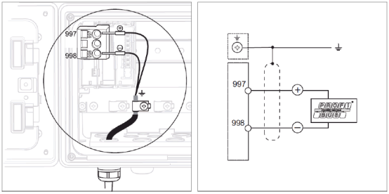
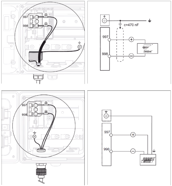
Note: The allowable supply voltage range is 9 to 32 V DC.
2.2 Sensor Wiring
2.2.1 Analog Sensor Wiring (Conductive Sensor)

- Connect the green, white, and yellow temperature wires to terminals 112, 113, and 111 respectively.
- Connect the colored measurement signal wires to terminal 219 (main wire) and terminal 220 (auxiliary wire) respectively.
- The sensor cable shield must be grounded.
2.2.2 Analog Sensor Wiring (Inductive Sensor)
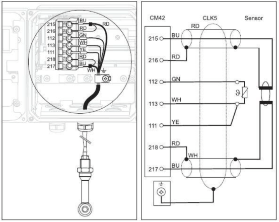
- Connect the green, white, and yellow temperature wires to terminals 112, 113, and 111 respectively.
- Connect the white-blue (wire color and core color) and white-red measurement signal wires to terminals 217 and 218 respectively, and connect the red-blue and red-red measurement signal wires to terminals 215 and 216 respectively.
- The sensor cable shield must be grounded.
2.2.3 Memosens Digital Sensor Wiring
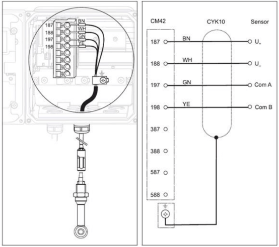
- Connect the brown, white, green, and yellow cable wires to terminals 187, 188, 197, and 198 respectively.
- The sensor cable shield must be grounded.
Note: Ensure all cable glands are tightened and sealed.
3. Key Functions
The CM42 transmitter uses soft keys and a browser for operation. The specific functions are as follows:
- Press soft key: directly select menu
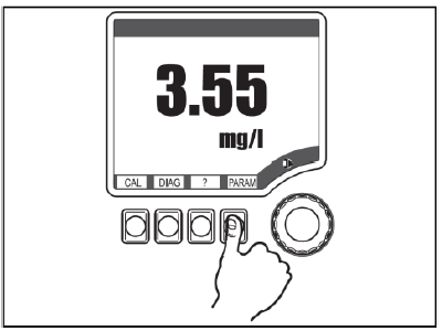
- Rotate browser: move cursor in menu
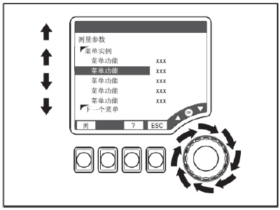
- Press browser: select function
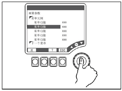
- Rotate browser: change value
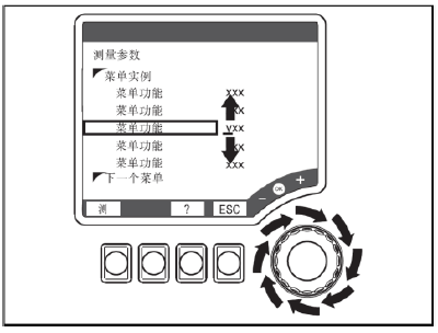
- Press browser key: accept new value
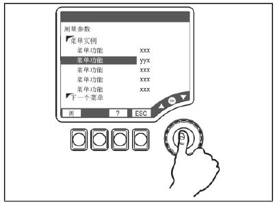
4. Settings
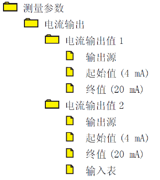
4.1 Range Setting
Set the "start value" and "end value" under the "Measurement Parameters/Current Output" menu. The specific menu location is as follows:
4.2 Transmitter Reset
Under the "Diagnostics/Maintenance Service/Factory Default Settings" menu, select "Factory Default Settings". The device will restart, and all settings will be reset to factory defaults.
5. Calibration
Enter the "Calibration" menu, select "Electrode Constant Calibration", and follow the menu prompts to complete calibration. The main steps are as follows:
- Remove the sensor from the medium, rinse with water, and dry it.
- Place the sensor in the calibration solution to start calibration. "Running" is displayed.
- Enter the conductivity value of the calibration solution. "Running" is displayed.
- After calibration, the status is displayed: whether the calibration is valid. Select "Store data for adjustment" or "Discard data". Upon success, the new electrode constant is displayed, and the new electrode constant will automatically overwrite the original electrode constant.
6. Common Fault Codes
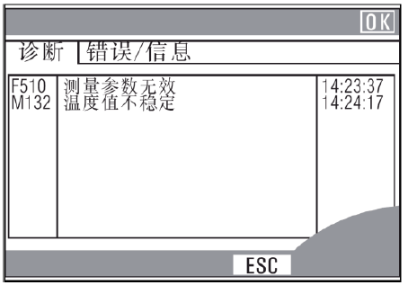
The transmitter continuously performs self-monitoring. If the device detects an error, a red alarm LED will light up. Information about the error can be read in the "Diagnostics/Error Messages" menu. An example is as follows: