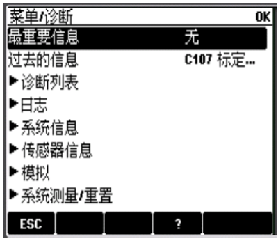
CM44X Transmitter Conductivity Commissioning Overview
When the CM44X transmitter is used with a conductivity sensor, steps such as installation, wiring, parameter setting, and calibration need to be completed. This article organizes the key operations in commissioning order to help engineering technicians and procurement personnel quickly grasp them.
Before commissioning, please confirm the power supply specifications on the transmitter nameplate and prepare the corresponding installation accessories and sensors.
1. Installation Methods
The CM44X has 3 installation methods, which can be selected according to on-site pipe or wall conditions.
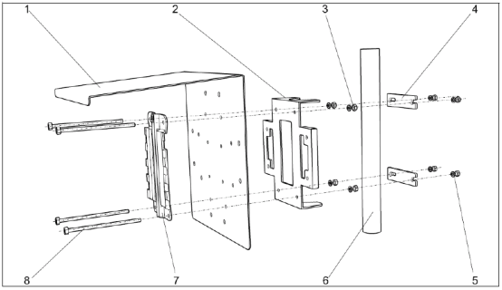
1.1 Vertical Pipe Installation
Suitable for vertically oriented pipes, with the transmitter fixed to the pipe.
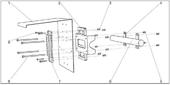
1.2 Horizontal Pipe Installation
Suitable for horizontally oriented pipes. During installation, pay attention to the transmitter orientation and readability.
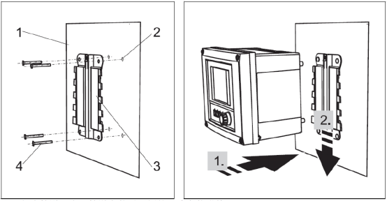
1.3 Wall Mounting
Suitable for occasions without pipes or requiring centralized installation, fixed directly on the wall.
Note: Vertical pipe and horizontal pipe installation require additional ordering of installation accessories.
2. Wiring Steps
2.1 Power Wiring
Connect the power supply according to the wiring diagram, and pay attention to distinguishing the power supply type.
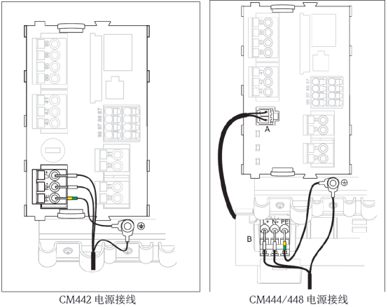
Note: Please check clearly whether the CM44X nameplate indicates 220VAC or 24VDC power supply to avoid incorrect connection and damage to the device.
2.2 Conductivity Sensor Wiring
Connect the sensor cable and current output according to the following requirements.
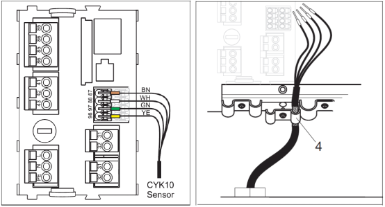
- Connect the four cable wires brown, white, green, and yellow to terminals 87, 88, 97, and 98 respectively.
- The shielding layer of the sensor cable must be grounded.
- Connect the current output to terminals 31 and 32; the current output is an active output.
Note: Ensure that all cable glands are tightened and sealed to ensure the protection rating.
3. Key Function Description
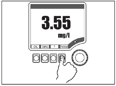
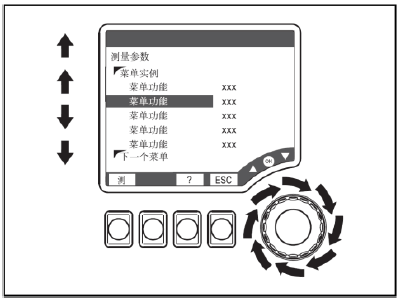
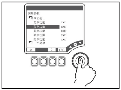
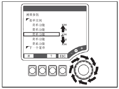
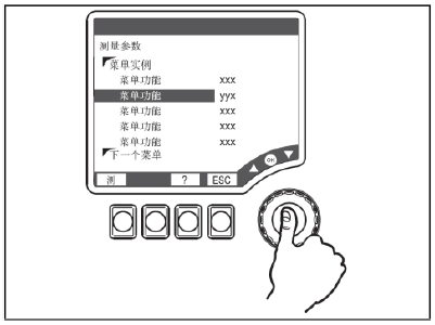
The CM44X uses a combination of soft keys and a browser for operation. Familiarity with the keys can improve commissioning efficiency.
- Press soft key: directly select the menu.
- Rotate browser: move the cursor within the menu.
- Press browser: select the function.
- Rotate browser: change the value.
- Press browser key: accept the new value.
4. Parameter Setting
4.1 Range Setting
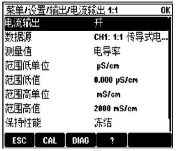
Enter the "Menu/Setup/Output/Current output x:x" menu and set the "Range low value" and "Range high value".
4.2 Transmitter Reset
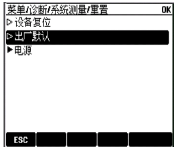
Enter the "Menu/Diagnostics/System measurement/Reset" menu, select "Factory default", and reset the transmitter.
5. Calibration Operations
5.1 Air Calibration
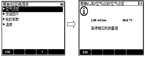
Before calibration, clean and dry the probe and place it in air. Enter "Menu/Calibration/Conductivity" and select "Air set", then follow the menu prompts.
After successful calibration, the air calibration value is displayed and you are asked whether to adjust the calibration data; after failed calibration, you are prompted whether to calibrate again.
5.2 Electrode Constant Calibration
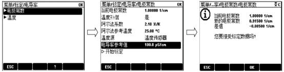
Enter "Menu/Calibration/Conductivity" and select "Electrode constant", follow the menu prompts, and set the "Conductivity reference value" for calibration.
After successful calibration, the new electrode constant is displayed and you are asked whether to adjust the calibration data; after failed calibration, you are prompted whether to calibrate again. The new electrode constant will automatically overwrite the original electrode constant.
6. Common Fault Codes
Fault codes and their meanings are automatically displayed on the measurement interface; you can enter "Menu/Diagnostics" to view fault codes, and press the "? key" to view the fault meaning.