CCM253 Residual Chlorine Transmitter Basic Commissioning Guide
The CCM253 transmitter is dedicated to the measurement of residual chlorine, chlorine dioxide, and total chlorine, and is widely used in water treatment, chemical, and other fields. This article introduces commissioning points step by step from installation, wiring, keypad operation, settings, calibration to maintenance, helping engineering and technical personnel and procurement personnel get started quickly.
1. Installation Methods
The CCM253 offers three installation methods, which can be selected according to the on-site environment.
1.1 Wall Mounting
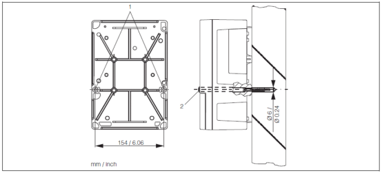
Use the two Ø6 holes at position 1 on the back of the transmitter to secure it to the wall with screws. At the factory, these two holes are plugged with black plugs (position 2), which must be removed before installation.
1.2 Pipe Mounting
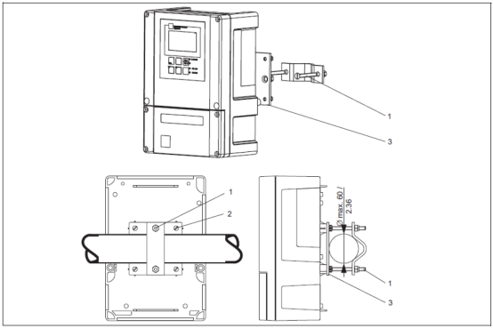
Vertical or horizontal pipe mounting can be used. During installation, use the four M5 threaded holes on the back of the transmitter (position 2). The maximum pipe diameter is Ø60. Pipe mounting requires additional mounting accessories to be ordered separately.
1.3 Weather Protection Cover Mounting
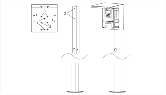
The weather protection cover must be ordered separately as an accessory. If the transmitter is installed outdoors in an open environment, it is recommended to use a weather protection cover to protect the instrument.
1.4 Flow-Through Mounting Bracket Measurement System
The flow-through mounting bracket (such as CCA250) and the transmitter form a complete measurement system, as shown in the diagram below.
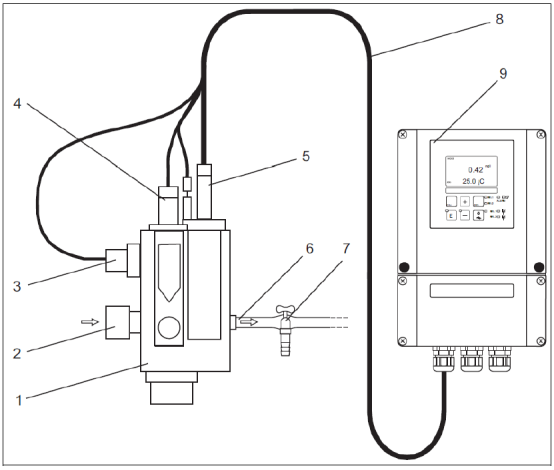
- 1 CCA250 flow-through mounting bracket
- 2 Medium inlet
- 3 Inductive switch, for flow monitoring
- 4 Mounting position for pH/ORP sensor
- 5 Residual chlorine measurement sensor
- 6 Medium outlet
- 7 Sampling port
- 8 Measuring cable
- 9 Transmitter
2. Wiring
Before wiring, confirm that the power supply is disconnected and operate according to the wiring diagram supplied with the unit. All cable glands must be tightened and sealed.
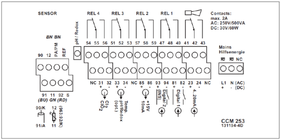
2.1 Connecting CCS140/141/240/241 Residual Chlorine and Chlorine Dioxide Sensors
- Attach the corresponding wiring diagram supplied with the unit to the terminals.
- The chlorine or chlorine dioxide sensor has an integrated cable: green to terminal 11, black to terminal 12, K to terminal 90, red A to terminal 91, shield to terminal S.
- Connect the pH sensor measurement and reference signals to the "pH" and "REF" terminals respectively; connect the brown equipotential line to the "PA/PM" terminal.
- Terminals marked "NC" and unmarked terminals are not connected.
- Connect the 220VAC power supply to terminals L1 and N; connect the 24VDC power supply to terminals + and -.
- Connect the first current output (residual chlorine or chlorine dioxide) to terminals 31 and 32, and the second current output (temperature or pH, optional) to terminals 33 and 34. The current output is an active output.
2.2 Connecting CCS120 Total Chlorine Sensor
- Attach the corresponding wiring diagram supplied with the unit to the terminals.
- The total chlorine sensor has a TOP68 connector without a cable, and the CPK9-N*A1B cable must be used with it. Connect yellow and white to terminal 11, white to 90, color to terminal 12, green to 85, brown to 86. Connect the shield to terminal S.
- Terminals marked "NC" and unmarked terminals are not connected.
- Connect the 220VAC power supply to terminals L1 and N; connect the 24VDC power supply to terminals + and -. Connect one current output (total chlorine) to terminals 31 and 32, and the second current output (temperature, optional) to terminals 33 and 34. The current output is an active output.
Note: Ensure that all cable glands are tightened and sealed.
3. Keypad Functions
3.1 Basic Keypad Function Description
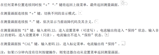
The keys on the transmitter panel are used for menu navigation, value modification, and confirmation operations. See the figure below for specific functions.
3.2 Keypad Lock and Unlock
To prevent accidental operation, the keypad can be locked. See the figure below for the lock and unlock method.

3.3 Relay Operation
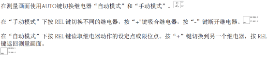
Relays can be used for alarms or control. See the figure below for the operation method.
4. Settings
Press the "M" key to enter the menu, and after entering the password "22", parameter settings can be performed.
4.1 Sensor Settings
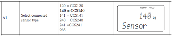
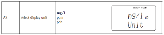
In the "A1" menu under the "SETUP 1" menu, select the corresponding sensor. Then select the corresponding unit in the "A2" menu.
4.2 pH Compensation Settings
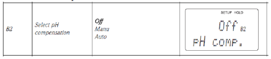
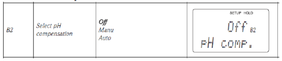
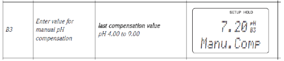
If the system has a pH sensor, select Manu in the "B2" menu under the "SETUP 2" menu. If the system does not have a pH sensor, also select Manu in the "B2" menu, and enter the actual pH value of the water sample in "B3".
4.3 Range Settings
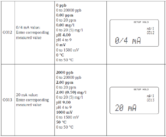
In the "Current Output" menu, set the range corresponding to 4-20mA. In O1, select the current output channel. When the instrument has dual-channel output, there are OUT1 and OUT2 options; when it has single-channel output, directly proceed to the next item. OUT1 is used as the current output for chlorine; OUT2 is used as the current output for temperature or pH.
4.4 Transmitter Reset
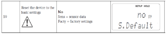
In the "S9" menu under the "Service" menu, select "Facty" to reset the transmitter.
5. Calibration
Press the "CAL" key and enter the password "22". Complete the slope calibration in the "Calibration" menu.
- In the "C11" menu, enter the Cl2 value measured in the laboratory and press the "CAL" key.
- After stabilization, it automatically enters the "C13" menu, displaying the calibrated slope.
- Press the "CAL" key, and the "C14" menu displays whether calibration passed or an alarm occurred.
- Press the "CAL" key, and in the "C15" menu select whether to save the calibration data, abandon it, or recalibrate.
6. Common Fault Codes
When the transmitter displays a fault code, refer to the table below for troubleshooting.

7. Sensor Maintenance
Regular maintenance can extend sensor life and ensure measurement accuracy.
- If the membrane is contaminated, clean the sensor.
- Replace the electrolyte once every quarter or every year, depending on the specific operating conditions.
- Replace the membrane regularly, depending on the specific operating conditions.
- Calibrate the sensor when necessary.
7.1 Cleaning the Sensor
- Remove the sensor from the flow-through bracket.
- Rinse gently with tap water, or soak in 1-5% hydrochloric acid for a few minutes.
7.2 Replacing the Membrane and Electrolyte
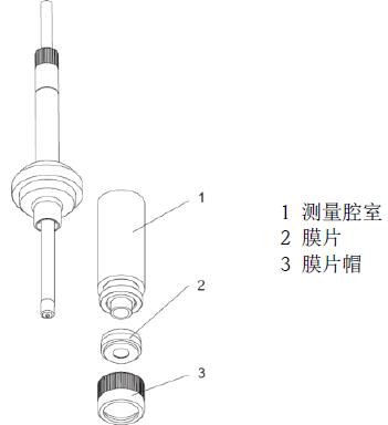
- Unscrew the measuring chamber (position 1).
- Unscrew the membrane cap at the front (position 3) and replace the membrane (position 1 internal thread).
- Add 7-8 ml of electrolyte to the measuring chamber until the liquid level reaches the internal thread of measuring chamber 1.
- Place the measuring chamber on a flat tabletop and tap it a few times to remove air bubbles in the electrolyte.
- Screw the measuring chamber filled with electrolyte onto the sensor. Excess electrolyte will flow out.
Note: The service life of the electrolyte is 1 year. Electrolyte that has turned yellow must not be used. After using the electrolyte bottle, tighten it to prevent the remaining electrolyte from being oxidized.
7.3 Storing the Sensor
During shutdown, if it can be ensured that there is water in the flow-through bracket, the sensor can be left in the bracket; if this cannot be ensured, the sensor must be removed and placed in a protective cap containing a moist sponge.
7.4 Activating the Sensor
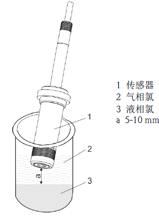
If the sensor is in a chlorine-free medium for a long time (>1 week), it will fail, have no response, or respond slowly. At this time, the sensor needs to be activated. Remove the sensor from the bracket, prepare 13% sodium hypochlorite (for CCS140/141) or chlorine dioxide (for CCS240/241) in a beaker. Place the sensor 5-10 mm above the liquid surface of the beaker. After the sensor's measured nA signal rises to several hundred nA, continue for another 20 minutes.