CM44X Transmitter Residual Chlorine Basic Commissioning Guide
The CM44X transmitter, combined with a residual chlorine sensor, is widely used for online residual chlorine monitoring in the water treatment industry. Correct installation, wiring, configuration, and calibration are key to ensuring measurement accuracy. This article systematically outlines the entire commissioning process for reference by engineering technicians and procurement personnel.
1. Installation Methods
The CM44X transmitter supports three installation methods, which can be flexibly selected according to on-site conditions.
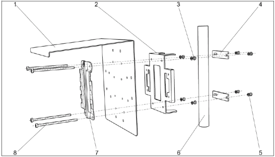
1.1 Pole Mounting
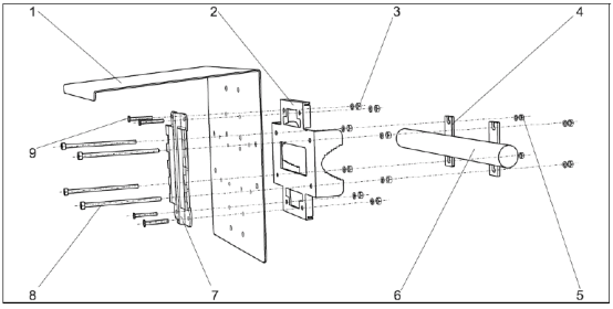
1.2 Horizontal Pole Mounting
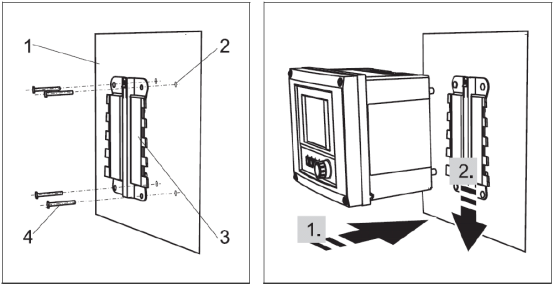
1.3 Wall Mounting
1.4 Measurement System Structure Diagram
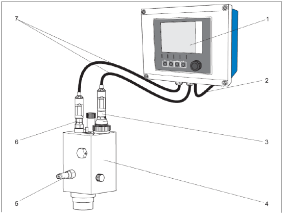
Description of components in the diagram:
- 1 Liquiline CM44X transmitter with protective cover
- 2 Transmitter power cable
- 3 CCS142D residual chlorine sensor
- 4 Flowfit CCA250 flow-through mounting bracket
- 5 Mounting bracket water inlet (water outlet is on the back, not shown in the diagram)
- 6 CPS71D pH sensor
- 7 CYK10 measuring cable
2. Wiring Steps
2.1 CM44X Power Wiring
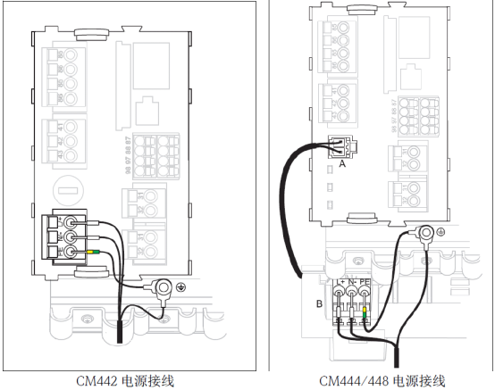
Note: Please check the CM44X nameplate carefully to confirm whether the power supply is 220VAC or 24VDC to avoid equipment damage caused by incorrect connection.
2.2 CCS142D Residual Chlorine Sensor Wiring
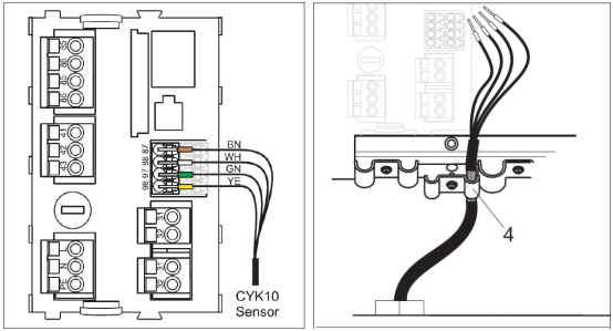
- Connect the four cable wires (brown, white, green, and yellow) to terminals 87, 88, 97, and 98 respectively.
- The sensor cable shield must be grounded.
- Connect the current output to terminals 31 and 32; the current output is an active output.
Note: Ensure all cable glands are tightened and sealed to prevent water ingress.
3. Keypad Functions
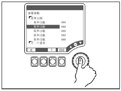
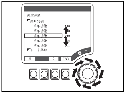
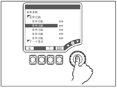
The CM44X uses a combined softkey and navigator operation method. The specific functions are as follows:
- Press the softkey: directly select the menu
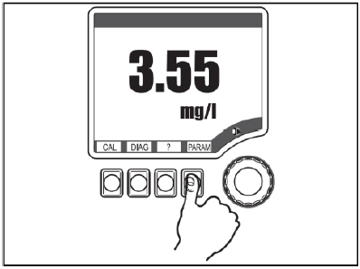
- Rotate the navigator: move the cursor in the menu
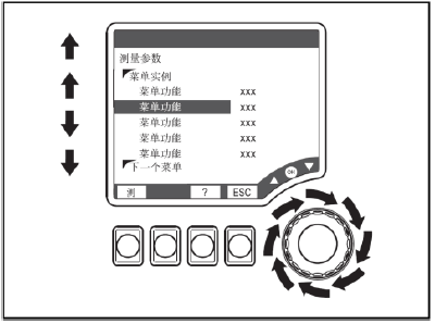
- Press the navigator: select a function
- Rotate the navigator: change a value
- Press the navigator: accept the new value
4. Parameter Settings
4.1 Range Setting
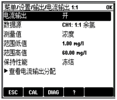
Under the "Menu/Setup/Output/Current output x:x" menu, set the range low value and range high value.
4.2 Transmitter Reset
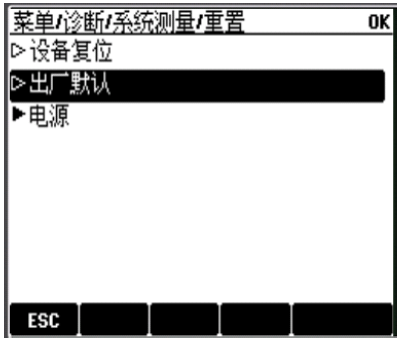
Under the "Menu/Diagnostics/System measurement/Reset" menu, select "Factory default" to reset the transmitter.
5. Calibration Steps
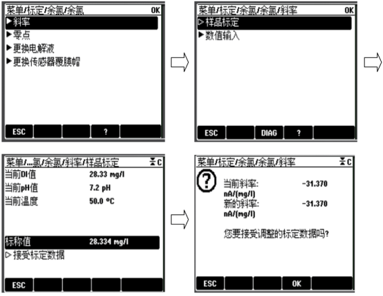
Enter "Menu/Calibration/Residual chlorine", select "Slope/Sample calibration", and follow the menu prompts to enter the nominal value to complete calibration. After successful calibration, the new slope is displayed and you are asked whether to accept the adjusted calibration data; after failed calibration, you are prompted whether to calibrate again.
6. Common Fault Codes
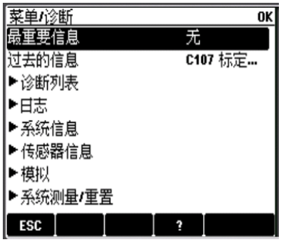
Fault codes and their meanings are automatically displayed on the measurement interface; you can enter "Menu/Diagnostics" to view fault codes and press the "?" key to view the meaning of the fault.
7. Sensor Maintenance
Regular maintenance can extend sensor life and ensure accurate measurement. The main maintenance items include:
- Clean the sensor when the membrane is contaminated.
- Replace the electrolyte quarterly or annually, depending on the specific operating conditions.
- Replace the membrane regularly, depending on the specific operating conditions.
- Calibrate the sensor when necessary.
7.1 Cleaning the Sensor
- Remove the sensor from the flow-through bracket.
- Rinse gently with tap water, or soak in 1-5% hydrochloric acid for a few minutes.
7.2 Replacing the Membrane and Electrolyte
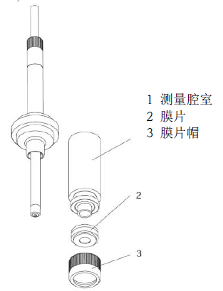
- Unscrew the measuring chamber (position 1).
- Unscrew the front membrane cap (position 3) and replace the membrane (position 2).
- Add 7-8 ml of electrolyte to the measuring chamber until the liquid level reaches the threads inside the measuring chamber.
- Place the measuring chamber on a flat tabletop and tap it a few times to remove air bubbles from the electrolyte.
- Screw the measuring chamber filled with electrolyte onto the sensor. Excess electrolyte will flow out.
Note:
- The electrolyte has a service life of 1 year; electrolyte that has turned yellow must not be used.
- Tighten the electrolyte bottle after use to prevent the remaining electrolyte from being oxidized.
7.3 Storing the Sensor
During shutdown, if it can be ensured that there is water in the flow-through bracket, the sensor can remain in the bracket; if this cannot be ensured, the sensor must be removed and placed in a protective cap containing a moist sponge.
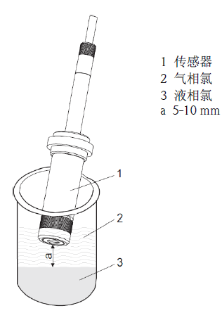
7.4 Activating the Sensor
If the sensor is exposed to a chlorine-free medium for an extended period (>1 week), it may fail, become unresponsive, or respond slowly. In this case, the sensor needs to be activated. Remove the sensor from the bracket and prepare 13% sodium hypochlorite in a beaker. Place the sensor 5-10 mm above the liquid surface of the beaker, wait until the sensor's measured nA signal rises to several hundred nA, and then continue for 20 minutes.