Basic Commissioning of CM44X Transmitter for Turbidity and Sludge Concentration
The CM44X transmitter is specifically designed for turbidity and sludge concentration measurement. Its commissioning process includes installation, wiring, key operations, settings, calibration, and fault handling. This article is intended for engineering and technical personnel as well as procurement, providing clear commissioning guidance.
1. Installation Methods
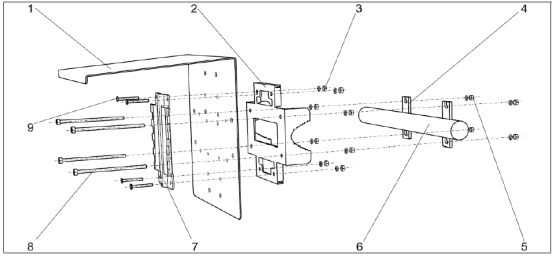
The CM44X supports three installation methods, which users can choose according to site conditions. Note: Vertical pipe and horizontal pipe installations require additional installation accessories to be ordered.
1.1 Vertical Pipe Installation
Suitable for vertical pipes. During installation, ensure the sensor is fully immersed.
1.2 Horizontal Pipe Installation
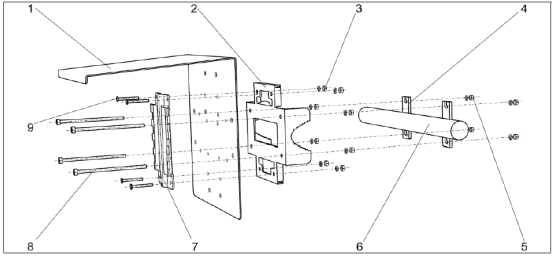
Suitable for horizontal pipes. During installation, pay attention to the flow direction and sensor position.
1.3 Wall-Mounted Installation
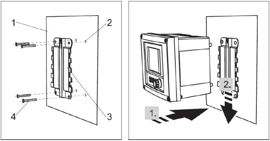
Suitable for wall mounting, saving space and facilitating operation.
2. Wiring Guide
Correct wiring is the foundation for ensuring the normal operation of the transmitter. Please be sure to follow the steps below.
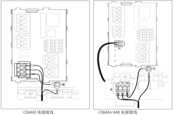
2.1 Power Wiring
First confirm the power supply type indicated on the CM44X nameplate: 220VAC or 24VDC, to avoid damage caused by incorrect connection.
2.2 Sensor Wiring
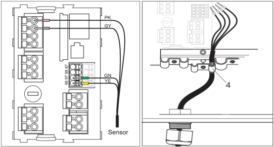
The sensor cable contains four wires, which need to be connected to the corresponding terminals. The current output is an active output, connected to terminals 31 and 32. Be sure to tighten and seal all cable glands.
- Connect pink, gray, green, and yellow to terminals 85, 86, 97, and 98 respectively.
- The sensor cable shield must be grounded.
- Connect the current output to terminals 31 and 32.
3. Key Functions
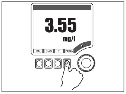
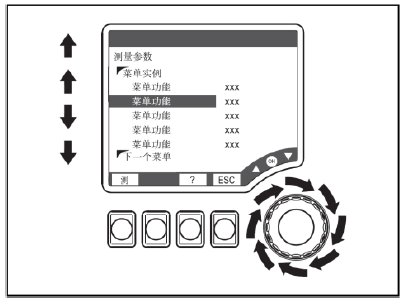
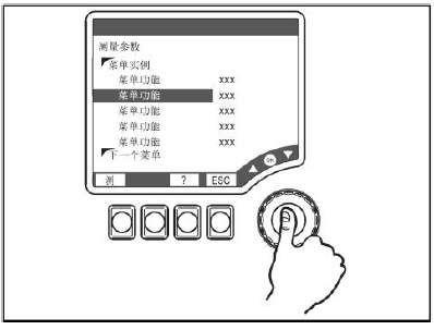
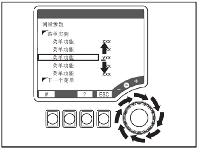
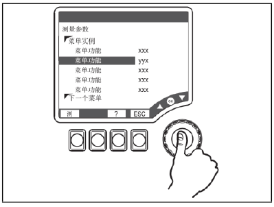
The CM44X uses a combination of soft keys and a navigator for operation. Familiarity with the keys can improve commissioning efficiency.
- Press soft key: Directly select the menu.
- Rotate navigator: Move the cursor in the menu or change values.
- Press navigator: Select a function or accept a new value.
4. Parameter Settings
Perform sensor application settings, range settings, and transmitter reset according to actual working conditions.
4.1 Sensor Application Settings
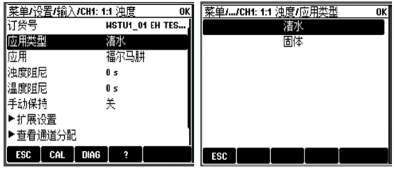
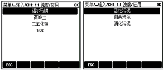
Under "Menu/Setup/Input/CH1:x:x/Application Type" and "Application", select the appropriate working condition. When the application type is "Clear Water" or "Solids", it corresponds to different application scenarios.
4.2 Range Settings
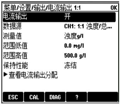
Under the "Menu/Setup/Output/Current Output x:x" menu, set the "Range Low Value" and "Range High Value".
4.3 Transmitter Reset
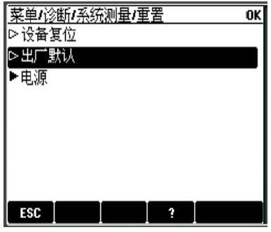
Under the "Menu/Diagnostics/System Measurement/Reset" menu, select "Factory Default" to reset the transmitter.
5. Calibration Steps
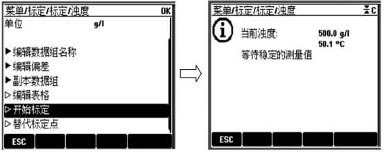
Calibration is key to ensuring measurement accuracy. Enter "Menu/Calibration/Turbidity" and follow the menu prompts step by step. Enter the laboratory test value into the nominal value. If multi-point calibration (up to 5 points) is selected, choose to calibrate the next test value. After calibration is completed, accept the calibration data and activate it.
6. Common Fault Codes
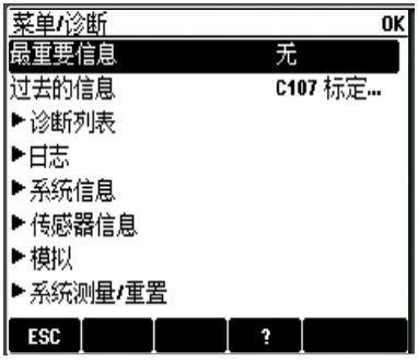
Fault codes and their meanings are automatically displayed on the measurement interface. You can enter "Menu/Diagnostics" to view fault codes and press the "?" key to view the fault meaning.