
CUM253/223 Transmitter Turbidity/Sludge Concentration Commissioning Guide
The CUM253/223 transmitter is specifically designed for turbidity and sludge concentration measurement. Correct installation and commissioning are key to ensuring measurement accuracy. This guide covers installation, wiring, keypad operation, parameter setting, calibration, and troubleshooting to help engineering and technical personnel efficiently complete instrument commissioning.
1. Installation Methods
The CUM253 offers three installation methods to suit different site environments.
1.1 Wall Mounting
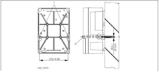
Use the two Ø6 holes at position 1 on the back of the transmitter to secure it to the wall with screws. At the factory, these two holes are plugged with black plugs (position 2), which must be removed during installation.
1.2 Pipe Mounting
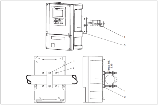
Vertical or horizontal pipe mounting can be used. During installation, use the four M5 threaded holes on the back of the transmitter (position 2). The maximum pipe diameter is Ø60.
1.3 Weather Protection Mounting
The weather protection cover protects the transmitter from harsh weather and must be ordered separately as an accessory.
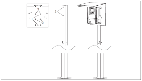
Note: Pipe mounting requires additional mounting accessories to be ordered. If the transmitter is installed outdoors in an open environment, it is recommended to use the weather protection cover to protect the instrument.
2. Wiring
The wiring for sensors CUS31 and CUS41 is the same. Please follow these steps:
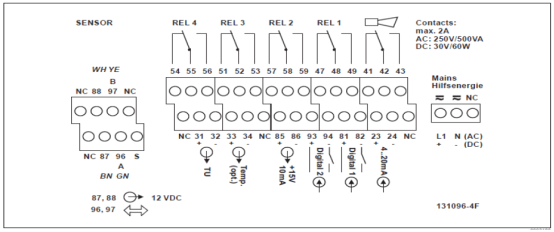
- Attach the corresponding wiring diagram supplied with the unit to the terminal block.
- Connect the brown and white sensor power wires to terminals 87 and 88 respectively.
- Connect the green, yellow, and black sensor signal transmission and shield wires to terminals 96, 97, and S respectively.
- Do not connect the terminals marked "NC" and unmarked terminals.
- Connect 220VAC power to terminals L1 and N; connect 24VDC power to terminals + and -.
- Connect the first current output (turbidity) to terminals 31 and 32, and the second current output (temperature, optional) to terminals 33 and 34. The current outputs are active outputs.
Note: Ensure that all cable glands are tightened and sealed.
3. Keypad Functions
Familiarity with the keypad functions is fundamental to operating the transmitter.
3.1 Basic Keypad Function Description
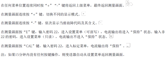
3.2 Keypad Lock and Unlock

3.3 Relay Operation
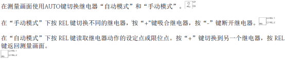
4. Parameter Setting
Parameter setting includes units, range, and reset, as described below.
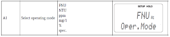
4.1 Unit Setting
Press the "E" key and enter password "22". In the "A1" menu under the "SETUP1" menu, select the desired unit.
4.2 Range Setting
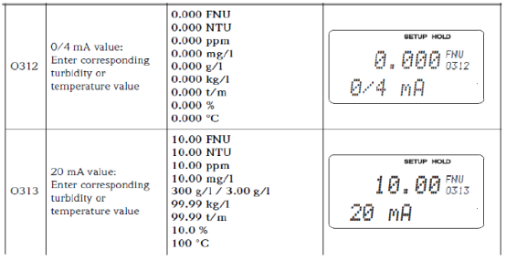
In the "Current Output" menu, set the range corresponding to 4-20mA. In O1, select the current output channel. For dual-channel output, OUT1 and OUT2 are available; for single-channel output, proceed directly to the next item. OUT1 serves as the current output for turbidity or sludge concentration, and OUT2 serves as the current output for temperature.
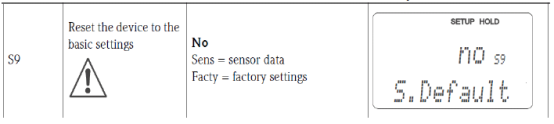
4.3 Transmitter Reset
In the "S9" menu under the "Service" menu, select "Facty" to reset the transmitter.
5. Calibration
Press the "CAL" key and enter password "22". Complete calibration in the "Calibration" menu.
- In the "C1" menu, select "1-Pt" and press the "CAL" key.
- Enter the calibration value in the "C151" menu and press the "CAL" key.
- After the value stabilizes, the "C152" menu displays the calibration status.
- In the "C153" menu, choose whether to save the calibration data, discard it, or recalibrate.
6. Common Fault Codes
The transmitter may display fault codes during operation. Common codes and their meanings are as follows:

If a fault code occurs, please refer to the manual or contact technical support.