
1. Check the Nameplate
Before wiring, be sure to check the instrument nameplate information to ensure it matches the order requirements.
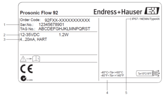
- Order code/serial number: Used to identify the instrument model and version.
- Power supply: 12~35VDC, power consumption 1.2W.
- Effective output: Such as 4-20mA, frequency, HART, etc.
- Permitted ambient temperature range: Ensure the working environment meets the requirements.
- Protection class: Such as IP67, indicating dust and water resistance.
2. Connection Compartment Nameplate Wiring Diagram
Open the connection compartment cover to see the internal wiring diagram. The terminal definitions are as follows:
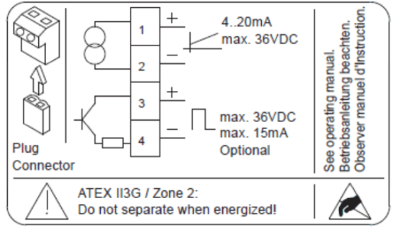
| Terminal No. | Function | Parameter |
|---|---|---|
| 1/2 | Power supply/current output | 4-20mA, max. 36VDC |
| 3/4 | Optional output | Max. 36VDC, max. 15mA |
3. Electrical Connection of Power Supply and Measurement Unit
Connect the power supply and signal lines correctly according to the output type.
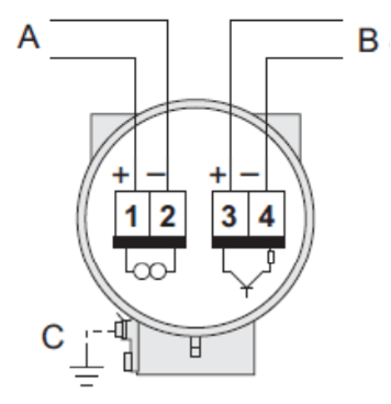
- A - HART: Power supply, current output. PROFIBUS PA: 1=PA+, 2=PA-; FOUNDATION Fieldbus (FF): 1=FF+, 2=FF-.
- B - Frequency output (optional): Not applicable to PROFIBUS PA and FF instruments; can also be used as pulse/status output.
- C - Ground terminal: Only applicable to the remote version.
4. Terminal Assignment of Prosonic Flow 92F
Refer to the figure below for specific terminal assignment to ensure correct wiring.

5. Electrical Connection of the Remote Version
The remote version requires connecting the transmitter and sensor. Pay attention to shielding and equipotential bonding.
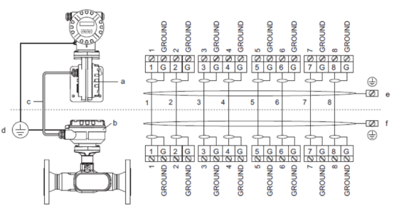
- a Connection compartment cover (transmitter)
- b Connection compartment cover (sensor)
- c Connecting cable (signal cable)
- d Equipotential bonding terminals of sensor and transmitter
- e Connect the shield to the ground terminal on the transmitter housing; keep the connecting line as short as possible
- f Connect the shield to the ground terminal on the connection compartment cover