
Prosonic 93 Pulse Output Setup Overview
Prosonic 93 is an ultrasonic level measurement instrument from Endress+Hauser that supports multiple output types, among which pulse output is often used for flow totalization, batch control, or driving external counters. Correctly setting up the pulse output ensures stable signal transmission and avoids measurement errors. Based on the actual operating interface, this article introduces the setup process step by step.
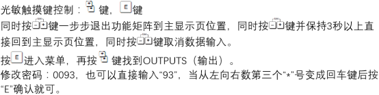
Preparation Before Setup
Before starting configuration, please confirm that the instrument is powered on and in measurement mode, and prepare the following information:
- The totalized quantity corresponding to the pulse output (such as volume or mass)
- The engineering unit value represented by each pulse (for example, 1 pulse = 1 L)
- Pulse width (usually 10–500 ms, depending on the external counter)
- Output type: active or passive pulse
If you are unsure about the parameters, refer to the output specifications on the instrument nameplate or in the technical manual.
Pulse Output Setup Steps
The following operations are based on the Prosonic 93 local display unit or FieldCare software. The menu path may vary slightly depending on the firmware version, but the logic is consistent.
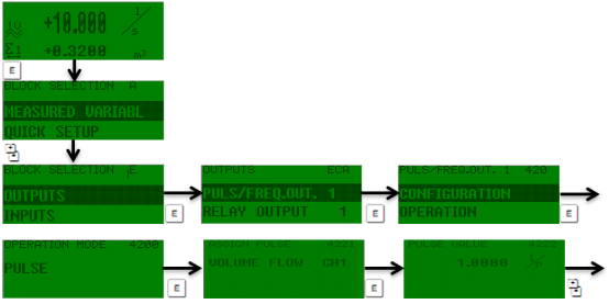
Step 1: Enter the Output Setup Menu
- Press the E key to enter the main menu.
- Use the + or - key to select “Setup” → “Output” → “Pulse Output”.
- Press the E key to confirm and enter the pulse output configuration page.
Step 2: Configure Pulse Output Parameters
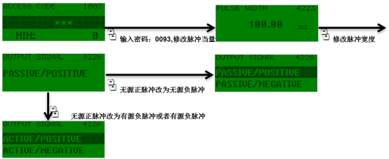
On the pulse output page, set the following parameters in sequence:
| Parameter Name | Description | Typical Value/Options |
|---|---|---|
| Output Mode | Select the pulse output function | Pulse totalization, batch control |
| Pulse Equivalent | The totalized quantity represented by each pulse | 0.1 L, 1 L, 10 L, etc. |
| Pulse Width | Pulse duration | 10 ms, 50 ms, 100 ms |
| Output Type | Active/Passive | Passive (default) |
| Maximum Pulse Frequency | Limit the output frequency | 10 Hz, 100 Hz |
After completing the settings, press the E key to save. If modification is needed, you can return to this page at any time to adjust.
Step 3: Wiring and Testing
After parameter setup, correct wiring and output verification are required:
- According to the output type, connect the pulse output terminals to the digital input of an external counter or PLC.
- Passive output requires an external power supply (usually 24 V DC); active output can directly drive the load.
- Use a multimeter or oscilloscope to monitor the pulse signal and confirm that the frequency and width match the settings.
- If the signal is abnormal, check the wiring polarity, load impedance, and whether the pulse equivalent is reasonable.
Common Issues and Precautions
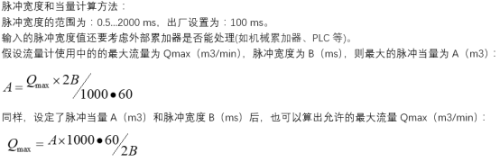
- Pulse loss: May be caused by too small a pulse width or slow response of the external counter. It is recommended to increase the pulse width or reduce the maximum frequency.
- Measurement deviation: Check whether the pulse equivalent is consistent with the totalized quantity unit, and recalibrate if necessary.
- No output signal: Confirm that the output mode is enabled and the wiring is correct.
- Electromagnetic interference: Use shielded cables and ensure single-ended grounding of the shield.
By following the above steps, you can efficiently complete the pulse output setup of the Prosonic 93 to meet the totalization and batch control requirements of industrial sites.