
I. Pre-installation Preparation for Promag 10 5XBB
Promag 10 5XBB is an electromagnetic flowmeter under Endress+Hauser, widely used in industrial process measurement. Correct installation and wiring are prerequisites for ensuring measurement accuracy. Before starting installation, be sure to read this guide and confirm that all accessories are complete.
1.1 Inspection and Confirmation
- Confirm that the flowmeter model matches the order and check for transportation damage on the appearance.
- Verify the nameplate parameters of the sensor and transmitter, such as nominal diameter, pressure rating, electrode material, etc.
- Prepare necessary tools: wrench, screwdriver, sealing gasket, cables, etc.
II. Installation Location and Pipeline Requirements
The installation location directly affects the measurement effect, and it must be ensured that the pipe is full and free of bubbles. The following are the key requirements.
2.1 Installation Location Selection
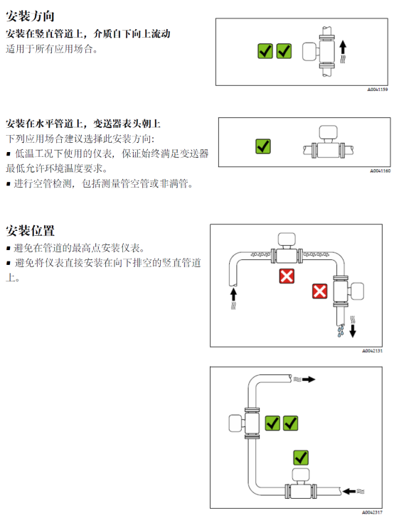
- Avoid installing at the highest point of the pipeline or at direct drain points to prevent bubble accumulation.
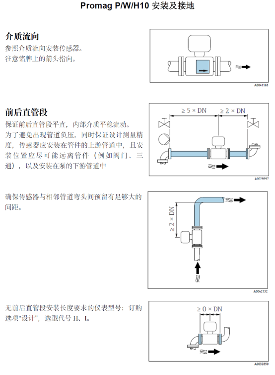
- Ensure that the fluid direction is consistent with the sensor arrow.
- For horizontal pipelines, the electrode axis should be horizontal to avoid sediment covering the electrodes.
2.2 Pipeline Conditions
- Ensure upstream and downstream straight pipe sections: 5D upstream and 3D downstream (D is the pipe inner diameter).
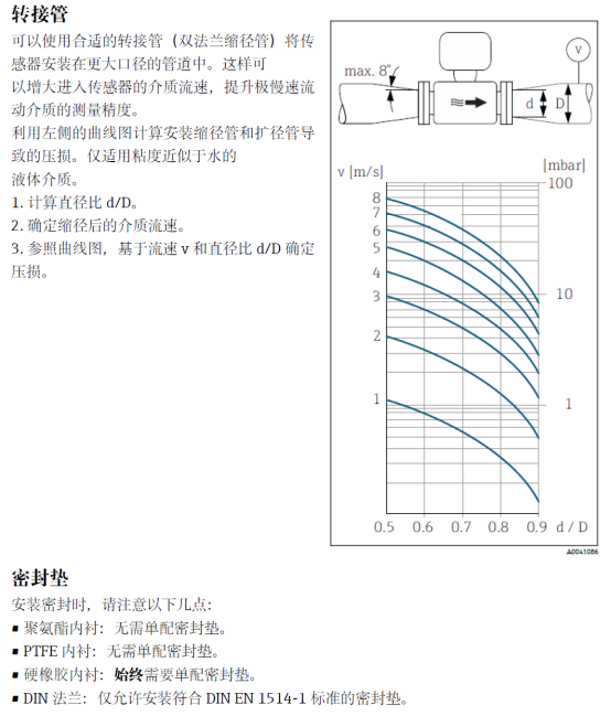
- The pipe inner diameter should be consistent with the sensor inner diameter; if necessary, use reducers.
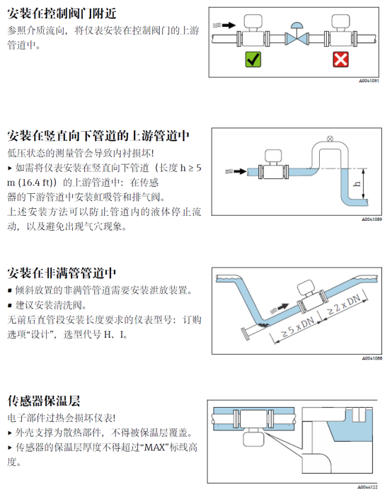
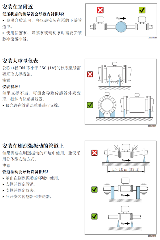
- If the pipeline vibrates strongly, additional support should be installed.
III. Mechanical Installation Steps
Perform mechanical installation according to the following steps to ensure good sealing and no leakage.
- Close the pipeline valve and drain the pipeline to ensure safety.
- Install the sealing gasket and align the sensor flange with the pipeline flange.
- Tighten the bolts evenly in a diagonal sequence to avoid excessive tightening on one side.
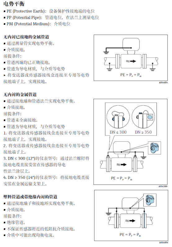
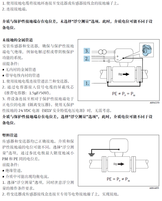
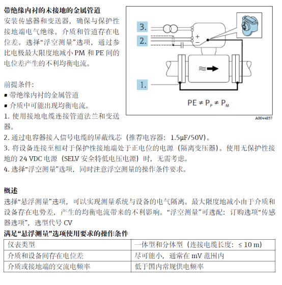
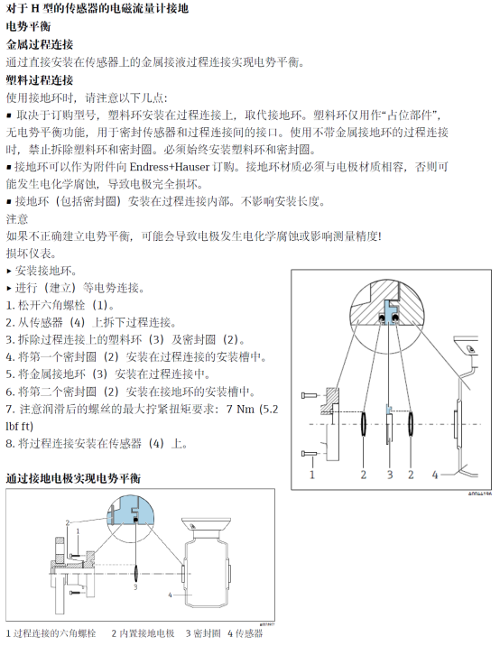
- Check the sensor grounding to ensure that the grounding ring or grounding electrode is correctly connected.
3.1 Grounding Requirements
Grounding is key to the anti-interference performance of electromagnetic flowmeters. The sensor grounding terminal must be reliably connected to the pipeline flange, or a grounding ring must be used. The grounding resistance should be less than 10Ω.
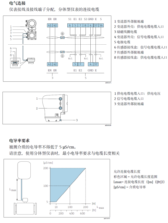
IV. Electrical Wiring
Before wiring, confirm that the power supply is disconnected and comply with local electrical codes.
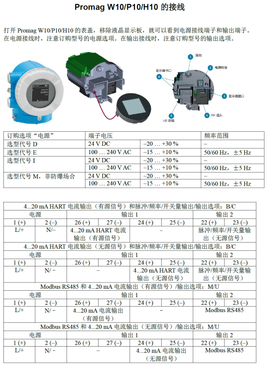
4.1 Terminal Description
| Terminal No. | Function | Cable Requirement |
|---|---|---|
| 1 | Power L+ | 24V DC or 220V AC |
| 2 | Power N- | Match power supply specifications |
| 3 | Current output + | Shielded twisted pair |
| 4 | Current output - | Shielded twisted pair |
| 5 | Pulse/frequency output | Shielded twisted pair |
| 6 | Grounding | Ground wire |
4.2 Wiring Steps
- Open the transmitter housing and locate the terminals.
- Pass the cable through the cable gland and strip the insulation by about 8 mm.
- Connect the power and signal cables according to the terminal description, paying attention to polarity.
- Tighten the gland to ensure sealing.
- Check that all connections are firm and free of short circuits.
V. Commissioning and Inspection
After installation and wiring are completed, commissioning is required to ensure normal operation.
5.1 Pre-power-on Inspection
- Confirm that the power supply voltage matches the nameplate.
- Check whether all wiring is correct and firm.
- Ensure that the sensor is filled with liquid and free of bubbles.
5.2 Parameter Settings
Set parameters such as range, damping time, and output type according to actual working conditions. For specific operations, please refer to the manual.
VI. Common Problems and Precautions
The following are some common problems and preventive measures.
- Large measurement fluctuation: Check whether grounding is good and whether the fluid is full in the pipe.
- No signal output: Check the power supply and wiring, and confirm whether the sensor is damaged.
- Zero drift: Ensure that the pipeline is filled with liquid and static, and perform zero calibration.
Following the above steps can ensure that the Promag 10 5XBB electromagnetic flowmeter is installed correctly and wired reliably, thereby obtaining accurate measurement results. If you have any questions, please contact technical support.