
Promag 50 Pulse Output Setup Overview
Promag 50 is an electromagnetic flowmeter launched by Endress+Hauser and is widely used in industrial flow measurement. Its pulse output function can convert flow signals into pulse signals for acquisition by external counters or PLCs. Correctly setting the pulse output is crucial to system accuracy.
This article introduces the setup method for the Promag 50 pulse output step by step, including hardware wiring, parameter configuration, and verification steps. It is suitable for reference by engineering and technical personnel and procurement personnel.
Preparation Before Setup
Required Tools and Materials
- Promag 50 flowmeter transmitter
- Digital multimeter (for verifying output)
- Small screwdriver (for wiring)
- Product specification or operation manual
Safety Precautions
- Ensure the flowmeter is powered off to avoid electric shock or equipment damage.
- Confirm that the working environment meets explosion-proof requirements (if applicable).
- Pay attention to polarity during wiring to avoid short circuits.
Pulse Output Hardware Wiring
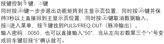
The pulse output of the Promag 50 is usually located on the transmitter's terminal block. Refer to the figure below to confirm the terminal positions:
Wiring steps:
- Open the transmitter housing and locate the output terminals (usually marked "Pulse" or "DO").
- Connect the pulse output positive pole (+) to the pulse input positive pole of the external device.
- Connect the pulse output negative pole (-) to the pulse input negative pole or common terminal of the external device.
- Ensure that the shielding layer of the shielded cable is grounded at one end to reduce interference.
After wiring is completed, check whether the connections are secure to avoid loose contacts.
Parameter Configuration Steps
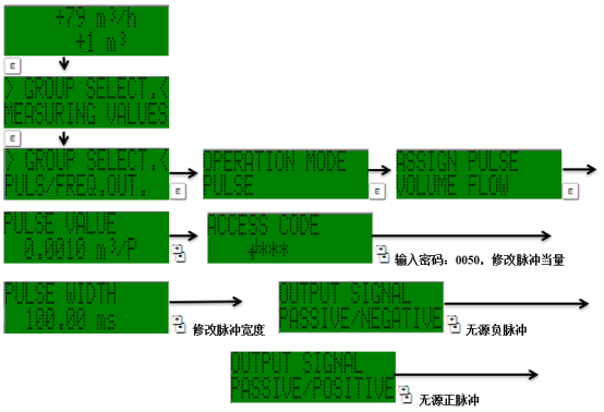
Set the pulse output parameters through the transmitter's operation interface. The figure below shows a typical menu structure:
Specific configuration steps:
- Enter the main menu and select "Setup" > "Output" > "Pulse Output".
- Set the pulse value: the flow volume represented by each pulse, for example, 1 pulse = 0.1 L. Adjust according to external device requirements.
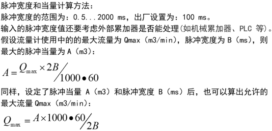
- Set the pulse width: usually selectable from 0.1 ms to 1000 ms, and it must match the response frequency of the external device.
- Select the output mode: such as "forward flow", "bidirectional flow", or "net flow".
- Save the settings and exit the menu.
The parameter setup interface may differ slightly depending on the firmware version. Please refer to the actual menu.
Parameter Description and Recommended Values
The table below lists the key parameters of the pulse output and their typical settings:
| Parameter | Description | Recommended Value |
|---|---|---|
| Pulse value | Flow volume corresponding to each pulse | According to external device requirements, e.g., 0.1 L/P |
| Pulse width | Duration of the pulse high level | 10 ms (general) |
| Output mode | Flow direction corresponding to the pulse | Forward flow |
| Maximum frequency | Maximum frequency of the pulse output | ≤ 10 kHz (depending on the pulse value) |
Note: The pulse value and maximum flow rate must match to avoid the frequency exceeding the receiving range of the external device.
Verification and Troubleshooting
After setup is completed, verify whether the pulse output is normal. The figure below shows an example output waveform:
Verification methods:
- Use a multimeter to measure the pulse output terminals; there should be a voltage jump.
- Connect a counter and observe whether the pulse count is proportional to the flow rate.
- If the output is abnormal, check the wiring, parameter settings, and power supply.
Common problems:
- No pulse output: Check the power supply, wiring, and output enable settings.
- Unstable pulse frequency: Check grounding and shielding to eliminate interference.
- Large counting deviation: Recalibrate the pulse value.
Summary
Correctly setting the Promag 50 pulse output can ensure accurate transmission of flow signals to the control system. Following the wiring, configuration, and verification steps in this article can effectively improve system reliability. For more detailed parameters, please refer to the official manual.