
Overview of Promag 53 Simulated Current Output
Promag 53 is an electromagnetic flowmeter introduced by Endress+Hauser, widely used in industrial flow measurement. Its simulated current output function allows simulating a 4-20 mA signal when there is no actual flow, for system commissioning and loop testing.
This function helps engineers verify whether the input channels of transmitters, PLCs, or DCS are functioning properly without actual fluid passing through the sensor. Correct use of simulated current output can significantly improve commissioning efficiency and maintenance safety.
Application Scenarios of Simulated Current Output
Commissioning and Acceptance
- When the pipeline is not filled with water, simulate standard current signals such as 4 mA, 12 mA, 20 mA, etc.
- Verify whether the analog input module of the host computer or PLC collects accurately.
- Check whether there is interference or disconnection in the signal loop.
Maintenance and Troubleshooting
- When suspecting abnormal transmitter output, replace the actual flow signal with simulated current.
- Quickly locate whether the fault is on the flowmeter side or the receiving side.
- Avoid misjudgment caused by actual flow fluctuations.
Promag 53 Simulated Current Output Setup Steps
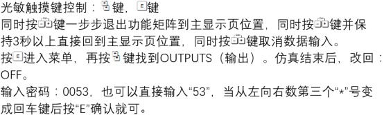
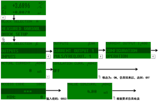
The following operations are based on the local display interface of the Promag 53 or FieldCare software. Please ensure the transmitter is in simulation mode and that interlocks with process control have been disconnected.
- Enter the main menu and select the "Diagnostics" or "Service" menu.
- Find the "Simulation" submenu and select "Current Output".
- Set the simulated current value, for example, 4.00 mA, 12.00 mA, 20.00 mA.
- Confirm output enable; the current output terminals will now output the set value.
- Measure the current at the receiving end to verify accuracy and linearity.
- After testing is complete, turn off the simulation function and restore normal measurement mode.
Simulated Current Output Parameters and Accuracy Comparison
The table below lists typical technical parameters of the Promag 53 simulated current output for reference in selection and verification.
| Parameter | Typical Value | Remarks |
|---|---|---|
| Output range | 4-20 mA | Extendable to 3.8-20.5 mA |
| Simulated current step | 0.1 mA | Set via keys or software |
| Accuracy | ±0.05% full scale | Reference condition: 25°C |
| Load resistance | ≤ 500 Ω | Depends on supply voltage |
| Simulation mode activation | Menu or FieldCare | Requires access password |
Common Issues and Precautions
No simulated current output
- Check whether the transmitter is in simulation mode rather than normal measurement mode.
- Confirm the current output terminal wiring is correct and the load resistance is not exceeded.
- Check whether the power supply is normal and whether the fuse is blown.
Large output value deviation
- Use a high-precision multimeter for measurement to eliminate measurement errors.
- Perform current output calibration (two-point calibration at 4 mA and 20 mA).
- Check whether the ambient temperature exceeds the compensation range.
Important note: Simulated current output is only for commissioning and maintenance. After testing, be sure to exit simulation mode; otherwise, the flowmeter will not be able to output the real flow signal, which may cause process accidents.
Summary
The simulated current output function of the Promag 53 is a practical tool for engineering commissioning and maintenance. Through the menu or FieldCare, 4-20 mA simulated signals can be quickly set to verify loop integrity. Following correct setup steps and safety precautions can effectively improve instrument commissioning efficiency and system reliability.