
1. Check the Nameplate
Before wiring, be sure to check the flowmeter nameplate information to ensure it matches the on-site requirements. The nameplate contains key parameters such as the order number, power supply specification, additional functions, and input/output configuration.
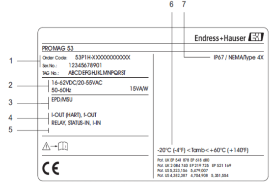
- Order number/serial number: Uniquely identifies the device, used for traceability and spare parts ordering.
- Power consumption: Note whether the power type is 220VAC or 24VDC to avoid incorrect connection.
- Additional information: Such as EPD/MSU (empty pipe detection electrode), ECC (electrode cleaning).
- Input/output: -OUT(HART) is current output (HART); f-OUT is frequency output; STATUSIN is status input.
- Reserved special product information: May include other special configurations depending on the order.
- Ambient temperature: Ensure the working environment temperature is within the allowable range.
- Protection class: Such as IP67, IP68, etc., which affects the installation method.
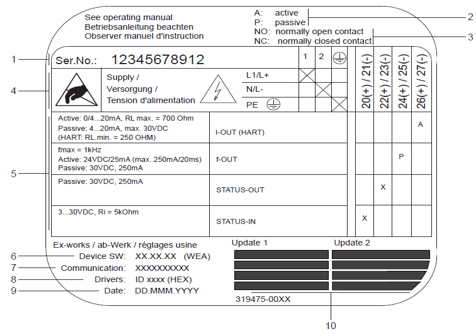
- Serial number: Unique device serial number.
- Current output configuration: A indicates active, P indicates passive.
- Relay configuration: NO indicates normally open, NC indicates normally closed.
- Terminal assignment: Terminal number 1: AC L1, DC L+; terminal number 2: AC N, DC L-.
- Configuration of terminals 20-27: Functions vary depending on the configuration.
- Software version: Software version currently installed on the device.
- Communication type: Such as HART, PROFIBUS PA, etc.
- Current communication software information: Device version and device description.
- Installation date: Device installation date.
- Update date: Update date at 6 to 9 o'clock.
2. Wiring Between the Sensor and Transmitter of a Remote Mass Flowmeter
For remote installation, the sensor and transmitter must be connected via a dedicated signal cable. Please wire correctly according to the figure below and the color correspondence.
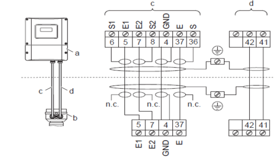
- a. Wall-mounted instrument housing connection part: Transmitter-side terminal.
- b. Sensor connection housing cover: Sensor-side terminal.
- c. Signal cable: Connects the sensor and transmitter.
- d. Coil current cable: Supplies power to the sensor coil.
- n.c. Not connected: Cable shield not connected.
The correspondence between cable colors and terminal numbers is as follows:
| Color | Terminal number |
|---|---|
| Brown | 5/6 |
| White | 7/8 |
| Green | 4-GND |
| Yellow | 37/36 |
3. Transmitter Wiring
The transmitter is available in three forms: aluminum housing, stainless steel housing, and wall-mounted instrument. The wiring methods are similar. The maximum cable inner diameter is 2.5 mm².
1. Aluminum Housing Transmitter Wiring
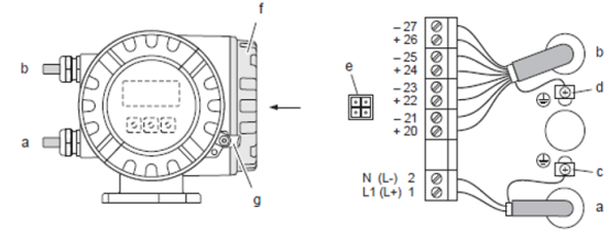
- a. Power supply cable: Terminal number 1: AC L1, DC L+; terminal number 2: AC N, DC L-.
- b. Signal cable: Terminal numbers 20-27.
- c. Protective grounding terminal: Connect to protective ground.
- d. Grounding terminal for signal cable shield: Connect the cable shield.
- e. Service interface: Connect service tools such as Fieldcheck and FieldCare.
- f. Terminal compartment cover: Close after wiring.
- g. Hexagonal screw cover lock: Secure the cover.
2. Stainless Steel Housing Transmitter Wiring
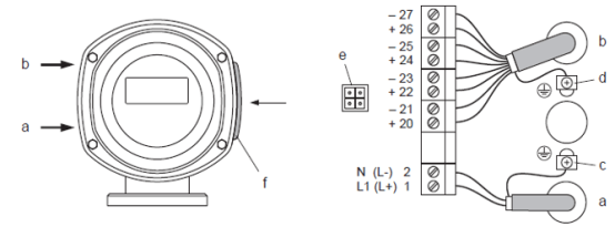
- a. Power supply cable: Terminal number 1: AC L1, DC L+; terminal number 2: AC N, DC L-.
- b. Signal cable: Terminal numbers 20-27.
- c. Protective grounding terminal: Connect to protective ground.
- d. Grounding terminal for signal cable shield: Connect the cable shield.
- e. Service interface: Connect service tools such as Fieldcheck and FieldCare.
- f. Terminal compartment cover: Close after wiring.
3. Wall-Mounted Instrument Wiring
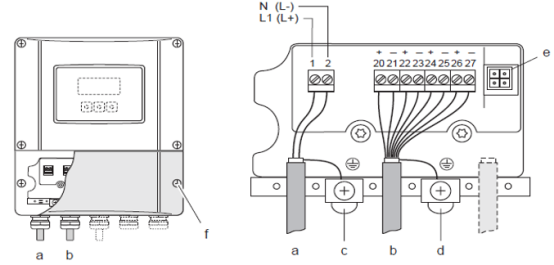
- a. Power supply cable: Terminal number 1: AC L1, DC L+; terminal number 2: AC N, DC L-.
- b. Signal cable: Terminal numbers 20-27.
- c. Protective grounding terminal: Connect to protective ground.
- d. Grounding terminal for signal cable shield: Connect the cable shield.
- e. Service interface: Connect service tools such as Fieldcheck and FieldCare.
- f. Terminal compartment cover: Close after wiring.
4. Terminal Assignment
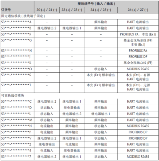
The Promag 53 provides various output types, and the terminal assignments are as follows:
1. Current Output
- Active/passive output selectable, electrically isolated, time constant selectable (0.01..100s), full scale value adjustable.
- Typical temperature coefficient: 0.005% o.r./°C (o.r. = of reading).
- Resolution: 0.5 μA.
- Active signal: 0/4...20mA, RL < 700Ω (HART: RL ≥ 250Ω).
- Passive signal: 4...20mA; operating voltage Vs is 18..30VDC, Ri ≥ 150Ω.
2. Pulse/Frequency Output
- Active/passive output selectable, electrically isolated (intrinsically safe Exi type only provides passive output).
- Active signal: 24VDC, 25 mA (within 20ms, max.250mA), RL > 100Ω.
- Passive signal: Open collector, 30V DC, 250 mA.
- Frequency output: Cutoff frequency 2...10000 Hz (fmax = 12500 Hz), 2..5000Hz for EEx-ia occasions; on/off ratio 1:1, maximum pulse width 10 s.
- Pulse output: Pulse value and pulse polarity selectable, maximum pulse width adjustable (0.05..2000 ms).
3. Status Output (Promag 50, Promag 53)
- Open collector, max. 30V DC / 250 mA, electrically isolated.
- Can be set to: fault message, empty pipe detection function (EPD), flow direction, limit value.
4. Relay Output (Promag 53)
- Normally closed (NC or break) or normally open (NO or make) contacts selectable (default setting: relay 1 is NO contact, relay 2 is NC contact).
- max. 30V / 0.5A AC; 60V / 0.1A DC, electrically isolated.
- Can be set to: fault message, empty pipe detection function (EPD), flow direction, limit value, batch control contact.