
I. Check the Transmitter Nameplate
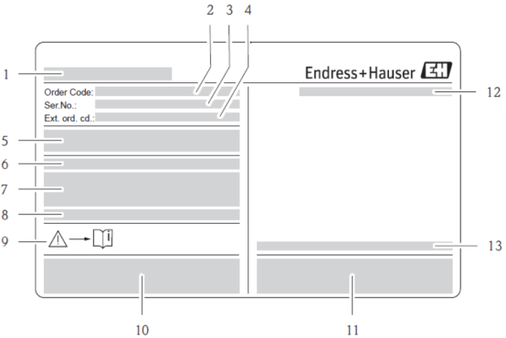
Before wiring, be sure to check the transmitter nameplate information to ensure that the device model, power supply, and output configuration are consistent with on-site requirements. The nameplate contains the following key information:
[Click image to enlarge]
- 1. Transmitter name
- 2. Order code
- 3. Serial number
- 4. Extended order code
- 5. Power supply/frequency, power consumption (note whether it is 220VAC or 24VDC)
- 6. Additional functions and software
- 7. Effective input/output
- 8. Reserved for special product information
- 9. Indicates operating structure/documentation
- 10. Reserved for certificates, approvals, and additional information on the device version
- 11. Patent rights
- 12. Degree of protection
- 13. Ambient temperature
II. Check the Terminal Compartment
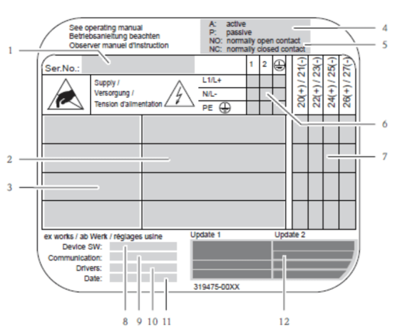
After opening the terminal compartment cover, check the internal label information to ensure that the terminal assignment matches the nameplate. The terminal compartment label contains the following:
[Click image to enlarge]
- 1. Serial number
- 2. Possible inputs and outputs
- 3. Input and output signals
- 4. Current output configuration
- 5. Relay configuration
- 6. Terminal assignment, power cable
- 7. Terminal assignment and input/output configuration (see points 4 and 5)
- 8. Currently installed device software version (device version SW)
- 9. Type of installed communication (communication)
- 10. Information on current communication software (driver: device version and device description) update date for points 6 to 9
- 12. Current update date specified for points 6 to 11
A: Active current output, no external power supply required;
P: Passive current output, external power supply required.
III. Wiring Between the Sensor and Transmitter of a Remote Mass Flowmeter
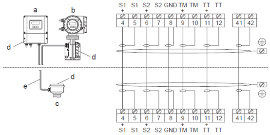
For remote installation, a dedicated connecting cable must be used between the sensor and transmitter. Select the correct instrument type according to the installation environment:
[Click image to enlarge]
- a. Wall-mounted instrument: Non-hazardous area and ATEX I13G/zone 2
- b. Wall-mounted instrument: ATEX I2G / Zone 1 / FM/CSA
- c. Remote version, flange version
- d. Connection components and cover of the connection housing
- e. Connecting cable
Terminal numbers for remote mass flowmeter wiring: 4/5 -- S1 gray, 6/7 -- S2 green, 8 -- GND yellow, 9/10 -- TM pink, 11/12 -- TT white, 41/42 -- brown.
IV. Transmitter Wiring
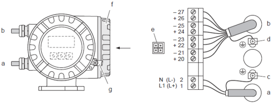
Transmitter wiring includes power cable, signal cable, and grounding connection. The wiring method is similar for different housing types; please follow the steps below:
1. Aluminum Housing Transmitter Wiring
[Click image to enlarge]
Connect the transmitter (aluminum housing); cable inner diameter: max. 2.5 mm².
- a. Power cable: Terminal No. 1: AC L1, DC L+; Terminal No. 2: AC N, DC L-
- b. Signal cable: Terminal Nos. 20--27
- c. Protective grounding terminal
- d. Grounding terminal for signal cable shield
- e. Service interface connection (Fieldcheck, FieldCare) service interface
- f. Housing cover for terminal compartment
- g. Hexagonal screw cover lock
2. Stainless Steel Housing Transmitter Wiring
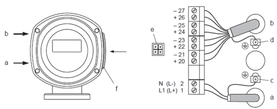
[Click image to enlarge]
Connect the transmitter (stainless steel housing); cable inner diameter: max. 2.5 mm².
- a. Power cable: Terminal No. 1: AC L1, DC L+; Terminal No. 2: AC N, DC L-
- b. Signal cable: Terminal Nos. 20--27
- c. Protective grounding terminal
- d. Grounding terminal for signal cable shield
- e. Service interface connection (Fieldcheck, FieldCare) service interface
- f. Housing cover for terminal compartment
3. Wall-Mounted Instrument Wiring
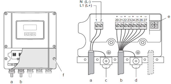
[Click image to enlarge]
Connect the transmitter (wall-mounted instrument); cable inner diameter: max. 2.5 mm².
- a. Power cable: Terminal No. 1: AC L1, DC L+; Terminal No. 2: AC N, DC L-
- b. Signal cable: Terminal Nos. 20--27
- c. Protective grounding terminal
- d. Grounding terminal for signal cable shield
- e. Service interface connection (Fieldcheck, FieldCare) service interface
- f. Housing cover for terminal compartment
V. Terminal Assignment
Terminal assignment defines the function and electrical characteristics of each input/output signal. Please wire correctly according to the actual configuration:
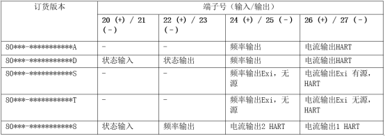
[Click image to enlarge]
| Signal Type | Electrical Characteristics | Parameters |
|---|---|---|
| Status input (auxiliary input) | Galvanically isolated | 330VDC, Ri=5kΩ, configurable |
| Status output | Open collector, galvanically isolated | max. 30V DC/250mA, configurable |
| Frequency output (passive) | Open collector, galvanically isolated | 30V DC/250mA |
| Frequency output | Full scale frequency | 2...1000Hz (fmax=1250Hz), on/off ratio 1:1, pulse width max. 2s |
| Pulse output | Pulse value and pulse polarity selectable | Pulse width adjustable (0.5...2000ms) |
| Current output (active/passive) | Galvanically isolated | Active: 4...20mA, R |