
1. Check the Transmitter Nameplate
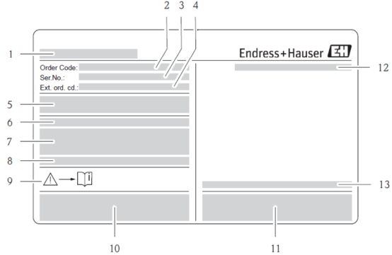
Before wiring, carefully check the transmitter nameplate information to ensure that the device model, power supply, and output configuration meet on-site requirements.
- Transmitter name: Confirm the device model.
- Order code: Used for spare parts ordering.
- Serial number: Unique identifier.
- Extended order code: Includes additional options.
- Power supply/frequency, power consumption: Note whether it is 220VAC or 24VDC.
- Additional functions and software: Check the software version.
- Effective input/output: Confirm the I/O configuration.
- Reserved special product information: Such as special certifications.
- Indicate operating structure/document: Operating manual number.
- Reserved certificates, approvals, and additional information on the device version: Such as ATEX, FM, etc.
- Patent rights: Patent information.
- Protection class: Such as IP67.
- Ambient temperature: Permissible range.
2. Check the Terminal Compartment
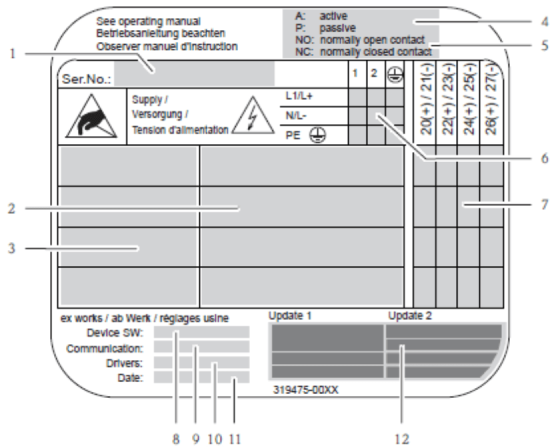
Open the terminal compartment cover and check the internal label to confirm wiring information.
- Serial number: Consistent with the nameplate.
- Possible inputs and outputs: Available I/O types.
- Input and output signals: Specific signal types.
- Current output configuration: Active/passive.
- Relay configuration: Normally open/normally closed.
- Terminal assignment, power cable: Power supply terminals.
- Terminal assignment and input/output configuration: Refer to points 4 and 5.
- Currently installed device software version: Device version SW.
- Type of installed communication: Communication protocol.
- Information on current communication software: Driver version and device description.
- Update date: Update date for points 6 to 9.
- Current update specifies date for points 6 to 11: Latest update date.
A: Active current output, no external power supply required; P: Passive current output, external power supply required.
3. Wiring Between Sensor and Transmitter of Separate Mass Flowmeter
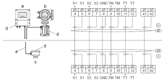
For separate installation, the sensor and transmitter are connected via a dedicated cable. Please select the correct version according to the installation environment.
- a. Wall-mounted instrument: Non-hazardous area and ATEX I3G6/zoe 2.
- b. Wall-mounted instrument: ATEX I2G / Zone 1 /FM/CSA.
- c. Separate version, flange version: Depending on sensor type.
- d. Connection parts and cover of connection housing: Ensure sealing.
- e. Connection cable: Terminal numbers and colors for separate mass flowmeter: 4/5--S1 gray, 6/7--S2 green, 8--GND color, 9/10--TM pink, 11/12--TT white, 41/42--brown.
4. Transmitter Wiring
The transmitter is available in three types: aluminum housing, stainless steel housing, and wall-mounted instrument. The wiring method is similar, but the housing structure is different.
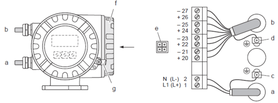
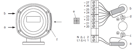
1. Connect the Transmitter (Aluminum Housing)
Cable inner diameter: max. 2.5 mm².
- a. Power cable: Terminal 1: AC L1, DC L+; Terminal 2: AC N, DC L-.
- b. Signal cable: Terminals 20--27.
- c. Protective ground terminal: Connect protective ground.
- d. Ground terminal for signal cable shield: Shield grounding.
- e. Service interface connection: Fieldcheck, FieldCare service interface.
- f. Cover screws and cover lock of terminal compartment: Ensure tight sealing.
2. Connect the Transmitter (Stainless Steel Housing)
Cable inner diameter: max. 2.5 mm².
- a. Power cable: Terminal 1: AC L1, DC L+; Terminal 2: AC N, DC L-.
- b. Signal cable: Terminals 20--27.
- c. Protective ground terminal: Connect protective ground.
- d. Ground terminal for signal cable shield: Shield grounding.
- e. Service interface connection: Fieldcheck, FieldCare service interface.
- f. Cover of terminal compartment: Ensure tight sealing.
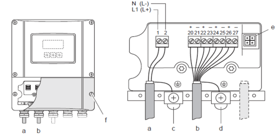
3. Connect the Transmitter (Wall-Mounted Instrument)
Cable inner diameter: max. 2.5 mm².
- a. Power cable: Terminal 1: AC L1, DC L+; Terminal 2: AC N, DC L-.
- b. Signal cable: Terminals 20--27.
- c. Protective ground terminal: Connect protective ground.
- d. Ground terminal for signal cable shield: Shield grounding.
- e. Service interface connection: Fieldcheck, FieldCare service interface.
- f. Cover of terminal compartment: Ensure tight sealing.
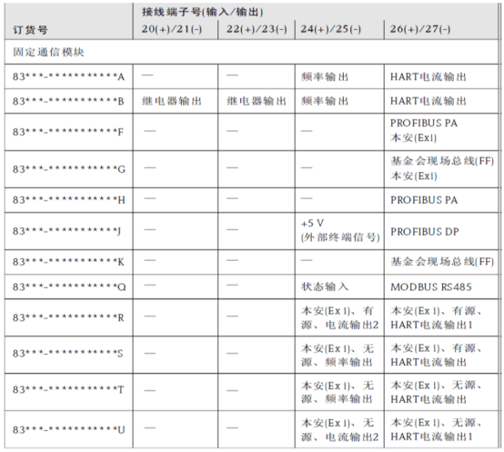
5. Terminal Assignment
Terminal assignment defines the function and electrical parameters of each input/output signal. Please wire according to the actual configuration.
| Function | Type | Electrical parameters |
|---|---|---|
| Status input (auxiliary input) | Galvanically isolated | 3-30V DC, Ri=5kΩ, configurable |
| Status output | Open collector | max. 30V DC/250mA, galvanically isolated, configurable |
| Frequency output (passive/active) | Open collector | 30V DC/250mA, galvanically isolated |
| Frequency output | Full scale frequency | ...1000Hz (fmax=1250Hz), on/off ratio 1:1, pulse width max.2s |
| Pulse output | Pulse value and polarity selectable | Pulse width adjustable (0.5...2000ms) |
| Current output (active/passive) | Galvanically isolated | Active: 4...20mA, R |