
Overview of Promass 83 Simulation Pulse Output
Promass 83 is a high-precision Coriolis mass flowmeter launched by Endress+Hauser and is widely used in industrial process measurement. Its simulation pulse output function allows pulse signals to be simulated when there is no actual flow, for system testing and fault diagnosis.
This function generates pulses with adjustable frequency through an internal signal generator, replacing the output of the real flow sensor, making it convenient to verify the response of downstream devices (such as PLCs and counters).

Application Scenarios of Simulation Pulse Output
System Commissioning and Verification
- When no medium is flowing through the pipeline, verify whether the pulse signal transmission between the flowmeter and the host computer is correct.
- Check the pulse counting function of the PLC or batch controller to ensure that wiring and configuration are correct.
Fault Troubleshooting
- When the actual flow output is abnormal, use the simulation pulse to determine whether it is a sensor fault or a downstream circuit problem.
- Quickly confirm whether the pulse output module is working properly and narrow down the fault scope.
Steps to Configure the Simulation Pulse Output
The simulation function can be enabled through the local display of the Promass 83 or commissioning software (such as FieldCare). The following is a typical operating procedure:
- Enter the menu: Setup → Simulation → Pulse Output.
- Select the simulation mode: Simulation Pulse, and set the output frequency (for example, 100 Hz).
- Activate simulation: switch Simulation to On. At this time, the pulse output terminal will output a square wave at the set frequency.
- Verify the signal: use an oscilloscope or frequency meter to measure the output terminal and confirm that the frequency matches the set value.
- Exit simulation: after testing is completed, switch Simulation to Off to restore normal measurement mode.
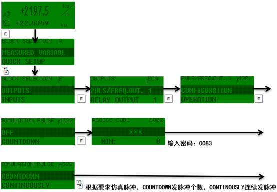
Description of Simulation Pulse Output Parameters
| Parameter | Description | Typical Value |
|---|---|---|
| Simulation frequency | Frequency of the output pulse, in Hz | 0.1~10000 Hz |
| Pulse width | Pulse duty cycle, usually 50% | 50% |
| Output level | Level standard of the pulse signal | 24V DC or passive |
| Simulation status | Enable or disable simulation | On/Off |
Precautions and Common Problems
Precautions
- During simulation, the flowmeter does not perform actual measurement, and the output signal does not represent real flow. It is only used for testing.
- Ensure that the simulation frequency does not exceed the maximum input frequency of downstream devices to avoid damage.
- After testing is completed, be sure to turn off simulation to avoid affecting normal production.
Common Problems
- No pulse output: Check whether simulation is activated, whether wiring is correct, and whether the power supply is normal.
- Frequency deviation: Confirm that the simulation frequency setting matches the range of the measuring device.
- Signal interference: Use shielded cables and ensure good grounding.
Summary
The simulation pulse output function of the Promass 83 provides engineering and technical personnel with a convenient commissioning method, which can effectively shorten system startup time and improve troubleshooting efficiency. Correctly setting parameters and observing precautions can ensure that the simulation process is safe and reliable.