
TMT180 Temperature Transmitter Wiring Overview
The TMT180 is a transmitter used for temperature measurement, and its wiring method directly affects measurement accuracy and equipment safety. Based on official documentation, this article explains in detail the correct connection methods for power and sensors.
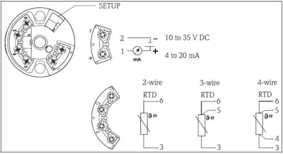
Power Wiring
The TMT180 uses a two-wire power supply, with a supply voltage range of 10-35 V DC. The power terminals are defined as follows:
- 1+: Power supply positive
- 2-: Power supply negative
Please ensure that the supply voltage is within the specified range to avoid equipment damage or measurement errors caused by overvoltage or undervoltage.
Sensor Wiring
The TMT180 only supports resistance temperature detector (RTD) input and cannot be connected to a thermocouple (TC). Depending on the RTD wiring configuration, the connections are as follows:
2-wire RTD
The 2-wire RTD connection is the simplest, but the lead resistance will introduce measurement error. The terminals are:
- One end connects to terminal 3
- The other end connects to terminal 6
3-wire RTD
The 3-wire configuration can compensate for lead resistance and improve measurement accuracy. The connection method is:
- One end connects to terminal 3
- The two wires at the other end connect to terminals 5 and 6 respectively
4-wire RTD
The 4-wire configuration completely eliminates the effect of lead resistance and provides the highest accuracy. The connection method is:
- The two wires at one end connect to terminals 3 and 4
- The two wires at the other end connect to terminals 5 and 6
Wiring Method Comparison
| RTD Type | Terminal 3 | Terminal 4 | Terminal 5 | Terminal 6 |
|---|---|---|---|---|
| 2-wire | One end | - | - | The other end |
| 3-wire | One end | - | Other end wire 1 | Other end wire 2 |
| 4-wire | One end wire 1 | One end wire 2 | Other end wire 1 | Other end wire 2 |
Precautions
- It is strictly prohibited to connect a thermocouple to the TMT180; otherwise, it may cause measurement errors or equipment damage.
- Before wiring, please confirm the power supply polarity. Reverse connection may damage the transmitter.
- For 3-wire and 4-wire configurations, please ensure that the lead resistances are equal to achieve optimal performance.
Correct wiring is the foundation for ensuring the long-term stable operation of the TMT180. Please be sure to operate according to the above instructions.