
TMT181 Temperature Transmitter Wiring Guide
The TMT181 is a commonly used temperature transmitter that supports thermocouple and RTD inputs. Correct wiring is the key to ensuring measurement accuracy and stable instrument operation. This article provides a detailed introduction to the power supply wiring and various sensor wiring methods for the TMT181.
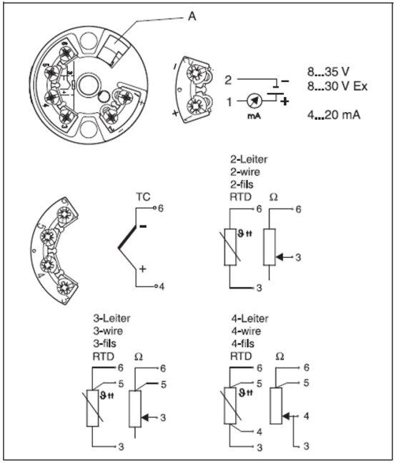
Power Supply Wiring
The TMT181 uses 2-wire power supply, with power and signal sharing two wires. Depending on the instrument type, the power supply voltage range differs:
- Non-explosion-proof instruments: 10-35 V DC
- Explosion-proof instruments: 10-30 V DC
The power supply terminals are 1+ and 2-, connected to the positive and negative poles of the power supply respectively.
Sensor Wiring
The TMT181 can be connected to a thermocouple or RTD. The specific wiring methods are as follows.
Thermocouple Wiring
The thermocouple signal is connected to terminals 4+ and 6-. Note the thermocouple polarity: the positive pole connects to 4, and the negative pole connects to 6.
RTD Wiring
RTD wiring methods differ depending on the wire configuration:
- 2-wire RTD: Connect to terminals 3 and 6.
- 3-wire RTD: The negative terminal connects to 3, and the two wires at the other end connect to 5 and 6 respectively.
- 4-wire RTD: The two wires at the negative terminal connect to 3 and 4, and the two wires at the other end connect to 5 and 6.
Wiring Precautions
- Ensure the power supply voltage is within the allowable range to avoid damaging the instrument.
- Before wiring, confirm the sensor type and wire configuration, and connect to the correct terminals accordingly.
- Use shielded cables with single-end grounding to reduce interference.
- Explosion-proof instruments must comply with relevant explosion-proof regulations.
After correct wiring, the TMT181 can stably output a 4-20 mA signal, achieving precise temperature measurement.