
TMT182 Temperature Transmitter Wiring Guide
The TMT182 is a universal temperature transmitter that supports thermocouple and RTD inputs. Correct wiring is key to ensuring measurement accuracy and stable instrument operation. This article will detail its power supply specifications and wiring methods for various sensor types.
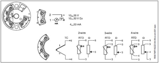
Power Supply and Output Wiring
The TMT182 uses a 2-wire configuration for both power supply and signal output, sharing two wires for power and signal. The terminal definitions are 1+ and 2-.
- Non-explosion-proof instruments: Supply voltage range is 10-35 VDC.
- Explosion-proof instruments: Supply voltage range is 10-30 VDC.
Please ensure correct power polarity to avoid damage to the instrument from reverse connection.
Sensor Wiring
The TMT182 can connect to thermocouples or RTDs, and the wiring terminals differ depending on the sensor type.
Thermocouple Wiring
When connecting a thermocouple, connect the positive signal to terminal 4 and the negative to terminal 6. Use compensation wires matching the thermocouple graduation.
RTD Wiring
RTDs support 2-wire, 3-wire, and 4-wire configurations. The specific terminal assignments are shown in the table below.
| RTD Type | Wiring Method |
|---|---|
| 2-wire | Connect to terminal 3 and terminal 6 |
| 3-wire | One end connects to terminal 3, and the two wires from the other end connect to terminal 5 and terminal 6 respectively |
| 4-wire | Two wires from one end connect to terminal 3 and terminal 4, and two wires from the other end connect to terminal 5 and terminal 6 |
It is recommended to prioritize 3-wire or 4-wire connections to eliminate measurement errors caused by lead resistance.
Wiring Precautions
- Before wiring, confirm that the power supply voltage is within the allowable range and ensure correct power polarity.
- Use a suitable screwdriver to tighten the terminals to avoid loose connections or short circuits.
- For explosion-proof instruments, explosion-proof regulations must be followed, and wiring must be done with the power off.
- Signal wires and power wires should be routed separately to avoid interference.
Following the above wiring specifications ensures long-term stable operation of the TMT182 temperature transmitter.