
TMT71 Temperature Transmitter Wiring Overview
The TMT71 temperature transmitter is a modular temperature transmitter commonly used in industrial sites, capable of converting RTD or thermocouple signals into standard 4~20mA current signal output. Correct wiring is the prerequisite for ensuring measurement accuracy and long-term stable operation.
This article focuses on the TMT71's terminal definitions, typical wiring methods, and precautions, suitable for engineering technicians and procurement selection reference.
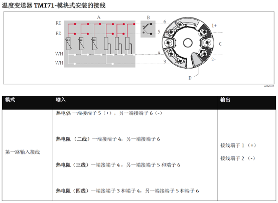
Terminal Definitions and Functions
The TMT71 typically uses screw-type terminals. The number of terminals may vary slightly between models, but the core functions are consistent. Before wiring, please check the nameplate and manual to confirm the correspondence between power supply and signal terminals.
Common Terminal Functions
- Power Terminals (+/-): Provide loop power to the transmitter, commonly DC 24V.
- Signal Output Terminals (+/-): Output 4~20mA standard current signal, connected to PLC or DCS analog input channels.
- Sensor Input Terminals: Connect RTD or thermocouple (TC), wired according to three-wire, four-wire, or two-wire configurations.
TMT71 Typical Wiring Steps
Taking two-wire wiring as an example, the power supply and signal share the same loop, which is the most commonly used method on site. The following steps apply to most TMT71 application scenarios.
- Confirm that the transmitter supply voltage is within the allowable range, typically DC 12~35V.
- Connect the positive power supply to the transmitter's positive terminal, and the negative power supply through the load (e.g., PLC input) back to the transmitter's negative terminal.
- Connect the RTD or thermocouple to the sensor input terminals according to the corresponding wiring configuration, paying attention to polarity.
- Check that the wiring is secure, avoiding loose connections or short circuits, then power on for testing.
- Use a multimeter or HART communicator to measure the output current and confirm the corresponding relationship with temperature is correct.
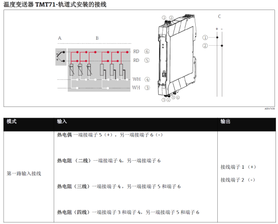
Comparison of Two-Wire and Four-Wire Wiring
Different wiring methods have a direct impact on measurement accuracy and anti-interference capability. Selection and construction should be determined based on site conditions.
| Wiring Method | Number of Wires | Accuracy Impact | Application Scenarios |
|---|---|---|---|
| Two-wire | 2 wires | Significantly affected by line resistance | Short distance, cost-sensitive occasions |
| Three-wire | 3 wires | Can compensate for part of line resistance | Conventional RTD measurement |
| Four-wire | 4 wires | Highest accuracy, eliminates line resistance | High-precision RTD measurement |
Wiring Precautions and Common Issues
Wiring quality directly affects transmitter lifespan and signal stability. The following points require special attention.
Construction Key Points
- Use shielded cables, with the shield grounded at one end, to reduce electromagnetic interference.
- Route power and signal lines separately, avoiding parallel laying with power cables.
- Use moderate torque on terminals to prevent damage or poor contact.
- Before powering on, use a multimeter to check the loop and confirm there are no short circuits or reversed connections.
Common Troubleshooting
- No output signal: Check supply voltage and loop polarity.
- Large output current deviation: Check sensor wiring configuration and range settings.
- Signal fluctuation: Check shield grounding and wiring tightness.
Following the above wiring specifications can effectively improve the measurement reliability and on-site maintenance efficiency of the TMT71 temperature transmitter.