
TMT72 Temperature Transmitter Wiring Overview
The TMT72 temperature transmitter is a high-performance field-mounted temperature transmitter widely used in industrial process control. Correct wiring is the foundation for ensuring its measurement accuracy and long-term stable operation. This article will provide a detailed introduction to the TMT72's wiring terminal definitions, wiring steps, and precautions.
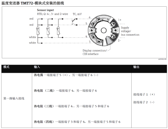
Wiring Terminal Definitions and Functions
The TMT72's wiring terminals are usually located inside the transmitter and can be seen by opening the housing. The terminal layout may vary slightly among different models, but the basic functions are the same. The following are common terminal definitions:
| Terminal Number | Function | Description |
|---|---|---|
| 1 | Power supply positive (+) | Connect to the positive pole of the DC power supply, usually 24V DC |
| 2 | Power supply negative (-) | Connect to the negative pole of the DC power supply, also serves as the negative pole of the signal loop |
| 3 | Signal output positive | Connect to the positive signal input of the control system or display instrument |
| 4 | Signal output negative | Connect to the negative signal input of the control system or display instrument |
| 5/6 | Sensor input | Connect to RTD or thermocouple sensor, depending on the model |
Note: Before actual wiring, be sure to refer to the specific product manual of the TMT72 to confirm the terminal numbers and functions.
Wiring Steps and Operation Guide
Follow the steps below to wire the TMT72 to ensure safety and correctness:
- Power off: Before wiring, ensure the power supply is turned off to avoid electric shock or equipment damage.
- Open the housing: Use appropriate tools to open the transmitter housing and expose the wiring terminals.
- Connect the sensor: According to the sensor type (such as Pt100, thermocouple), connect the sensor leads to the corresponding sensor input terminals (5/6). Pay attention to polarity; for thermocouples, use compensation wires.
- Connect the power supply: Connect the positive pole of the 24V DC power supply to terminal 1, and the negative pole to terminal 2.
- Connect the signal output: Connect the positive signal output to terminal 3, and the negative to terminal 4, and connect to the control system or display instrument.
- Check and tighten: Check whether all wiring is secure, with no short circuit or open circuit, then tighten the terminal screws.
- Restore the housing: After confirming the wiring is correct, reinstall the housing and ensure good sealing.
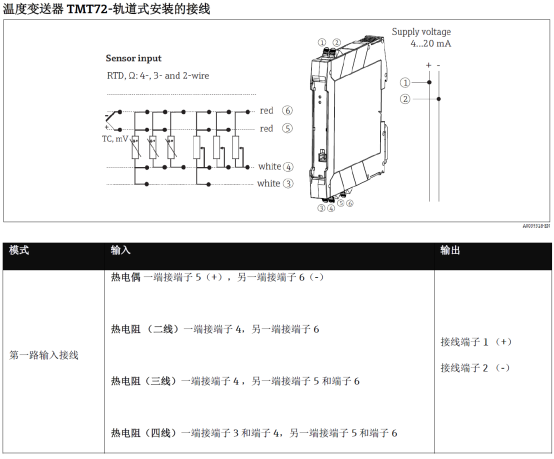
Typical Wiring Diagram and Configuration Examples
The above figure shows the typical connection method of the TMT72 with an RTD sensor, power supply, and control system. The following are common configurations:
- Two-wire connection: Power and signal share two wires, suitable for some models; pay attention to polarity.
- Four-wire connection: Power and signal are separate, improving anti-interference capability, recommended for long-distance transmission.
- Sensor connection: For RTDs, it is recommended to use three-wire or four-wire connection to eliminate the influence of lead resistance; for thermocouples, matching compensation wires must be used.
Ensure that the wiring is consistent with the transmitter configuration (such as sensor type, range), and configure via a handheld communicator or software if necessary.
Wiring Precautions and Common Problems
To avoid faults, pay attention to the following points during wiring:
- Power polarity: Reverse connection may damage the transmitter; be sure to confirm the positive and negative poles.
- Signal isolation: If the system requires isolation, use an isolated transmitter or add an isolator.
- Grounding: Ensure the transmitter housing is reliably grounded to reduce electromagnetic interference.
- Environmental protection: After wiring, ensure the housing is sealed to prevent moisture and dust from entering.
- Common problems: When there is no output signal, check the power supply, wiring polarity, and sensor connection; when the output deviation is large, check the sensor type and range settings.
Following the above guide can ensure correct wiring of the TMT72 temperature transmitter, improving system reliability and measurement accuracy. If you have any questions, please consult the manufacturer's technical support.