
TMT31 Temperature Transmitter Wiring Overview
The TMT31 temperature transmitter is a commonly used temperature measurement instrument in industrial sites. Whether its wiring is correct directly affects measurement accuracy and system stability. Based on official materials, this article summarizes the key wiring points of the TMT31 to help engineering personnel quickly complete installation.
Before wiring, please confirm the transmitter model, supply voltage, and sensor type, and comply with on-site safety regulations. The figure below shows the typical wiring layout of the TMT31.
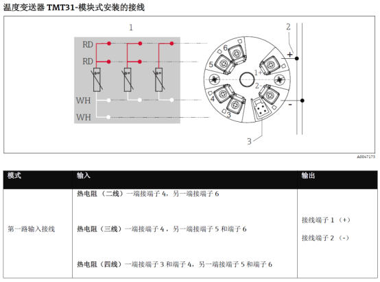
Terminal Definitions and Functions
The TMT31 usually uses pluggable screw terminals. The terminal numbering may vary slightly depending on the model version, but the basic functions are the same. Please refer to the product label.
Power and Signal Terminals
- Terminals 1 and 2: Usually power supply positive (+) and signal output positive (S+). Please refer to the nameplate for details.
- Terminal 3: Power supply negative (-) or signal loop negative (S-).
- Terminals 4, 5, 6: Used to connect RTD or thermocouple sensors.
The terminal functions of two-wire and four-wire transmitters are different and must be confirmed according to the actual model. It is recommended to use shielded cables, with the shielding layer grounded at one end.
Detailed TMT31 Wiring Steps
The following steps apply to common two-wire or four-wire TMT31 transmitters. Please adjust according to the actual configuration.
- Power off: Ensure the power is off to avoid damage caused by live wiring.
- Strip the wire: Strip about 5-7 mm of the cable outer sheath to expose the conductor, avoiding damage to the copper core.
- Connect the sensor: According to the sensor type (RTD or TC), connect the wires to the corresponding terminals. For example, a three-wire RTD needs to be connected to terminals 4, 5, and 6.
- Connect power and signal: Connect the power positive to terminal 1 and the signal positive to terminal 2 (if it is a two-wire system, power and signal share terminals 1 and 2).
- Tighten the terminals: Use a screwdriver to tighten the terminal screws to ensure reliable contact.
- Check and power on: After verifying that the wiring is correct, power on and test the output signal.
Comparison of Wiring Methods for Different Sensors
The TMT31 supports a variety of temperature sensors, and the wiring methods differ. The table below summarizes common configurations.
| Sensor Type | Wiring Terminals | Description |
|---|---|---|
| Two-wire RTD | 4, 5 | Resistance signal; lead resistance compensation is required |
| Three-wire RTD | 4, 5, 6 | Eliminates the effect of lead resistance; recommended |
| Four-wire RTD | 4, 5, 6 and spare terminals | High-precision measurement; requires constant current excitation |
| Thermocouple | 4, 5 | Requires cold junction compensation; observe polarity |
When choosing the wiring method, consider measurement accuracy, cable length, and cost. The three-wire RTD is the most common in industrial sites.
Wiring Precautions and Common Problems
To ensure long-term stable operation of the TMT31, pay attention to the following points during wiring.
Key Precautions
- Power polarity: Reverse connection may damage the transmitter, so be sure to confirm positive and negative.
- Signal isolation: If sharing a power supply with other equipment, an isolator is recommended.
- Cable selection: Use shielded twisted pair and keep away from power cables.
- Environmental protection: The terminals should be sealed to prevent moisture ingress.
Common Troubleshooting
- No output signal: Check whether the power supply is normal and whether the terminals are loose.
- Large output deviation: Check whether the sensor wiring is correct and whether the lead resistance matches.
- Signal fluctuation: Check the shielding layer grounding and whether there is electromagnetic interference.
Following the above guidelines can effectively improve the wiring efficiency and reliability of the TMT31. For a more detailed electrical connection diagram, please refer to the product manual.